Entering sections
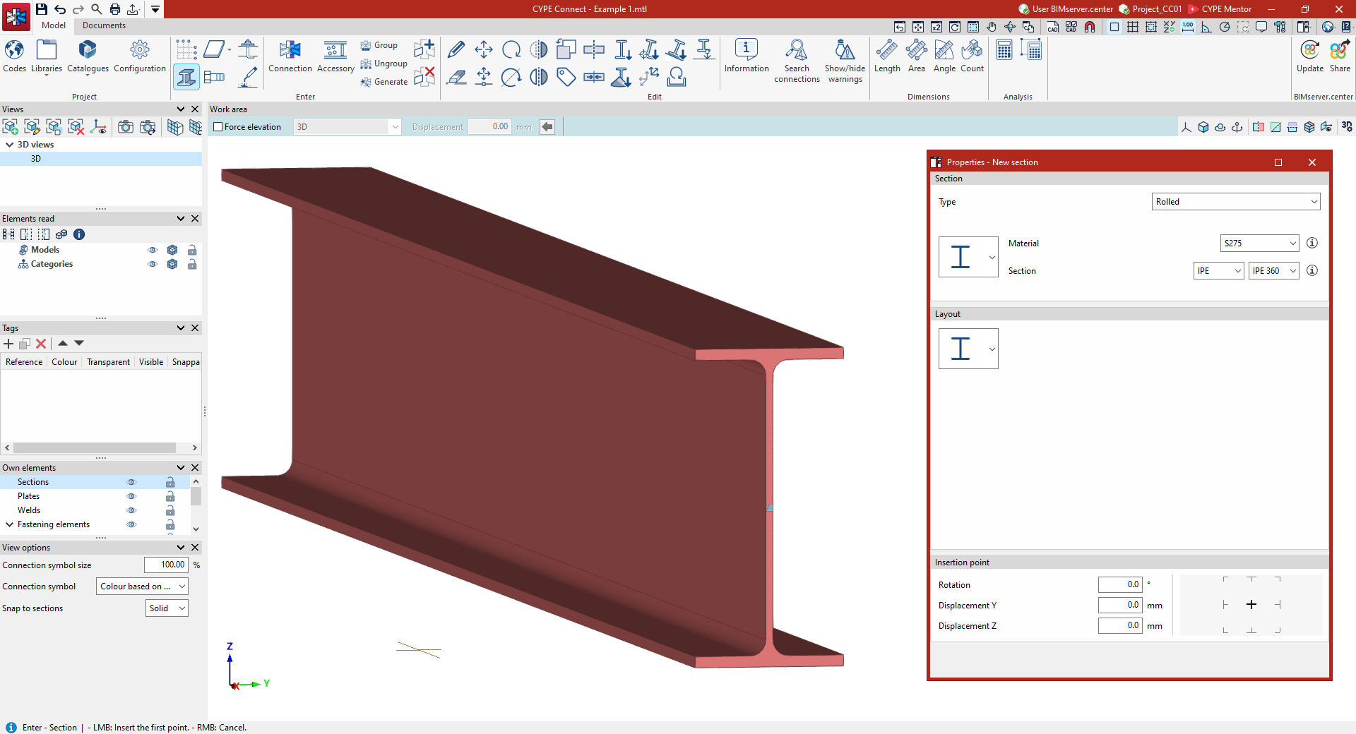
Sections can be entered directly. To do this, in the "Model" tab of the program’s main interface, select the "Section" option from the "Enter" section on the top toolbar.

Section
Defining section properties
In the window that appears when you click on the "Section" option, you can define the "Properties of the new section". First, select the "Type" from those available in the first drop-down menu:
- Hot-rolled section
- Built-up section with rolled steel plates
- Cold-formed section
- Hollow section
- Timber section
Next, in the drop-down menu, you can select the specific section type. For example, if you are using a "Rolled" section, the program allows you to choose from an I section, a U section, an angle section, a generic plate, a T section, a square bar or a round bar.
You can select the "Material" from the drop-down menu from those available in the library. Alternatively, if you click on the information button on the right now, you can view its "Reference", "Description" and material properties.
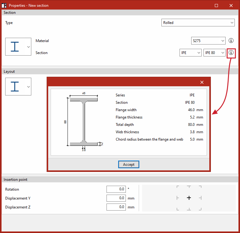
Next, the "Section" is defined by selecting a "Section series" directly from the available library, then a specific "Section" from that series using the drop-down menus. Similarly, if required, click the information button on the right to view its geometric properties, such as the section dimensions in the series, the thickness, or the root radius.
Next, in the drop-down menu under the "Layout" section, the section layout is specified (for example, for a double-T section, you can choose whether it is a simple section, with lateral plates, double welded-in box, or double or simple with haunches). Each of these options offers different configuration possibilities.
Finally, under "Insertion point", you can specify the "Rotation", "Y Displacement" and "Z Displacement" of the section along its local axes. On the right-hand side, you can specify the alignment point, either on the section’s axis, at the centre of one of its faces, or at one of its corners.
| Note: |
|---|
| The available sections and layouts can be viewed via this link. |
Adding a section to the work area
Once you have defined its properties, you must enter the section's geometry into the "Work area".
The section is defined by its start and end points; therefore, to insert it, you must select two points on the model using the left mouse button. You can control the position of the points using the various options for inserting elements in the workspace.
To help with these points, there are various tools available, such as the following:
- You can snap to the lines of a previously defined "Grid"
- To snap points from other elements already included in the model, check that these are selectable in the visibility options on the left-hand side and use the "Object reference" option.
- It is also useful to click on the "Allows dimensions to be defined as each element is entered" option so that you can enter the "Length" value for the section as you type it in.
- Furthermore, the "Orthogonality" option forces the section direction when it is entered.
- If required, you can work using the "Coordinate entry" method.
Additionally, if a template has been imported into the program, the "Template object snaps" available on the top toolbar are used.
Further sections can be entered by left-clicking on other points. Simply right-click the mouse to complete the operation and exit the command.