Entering plates
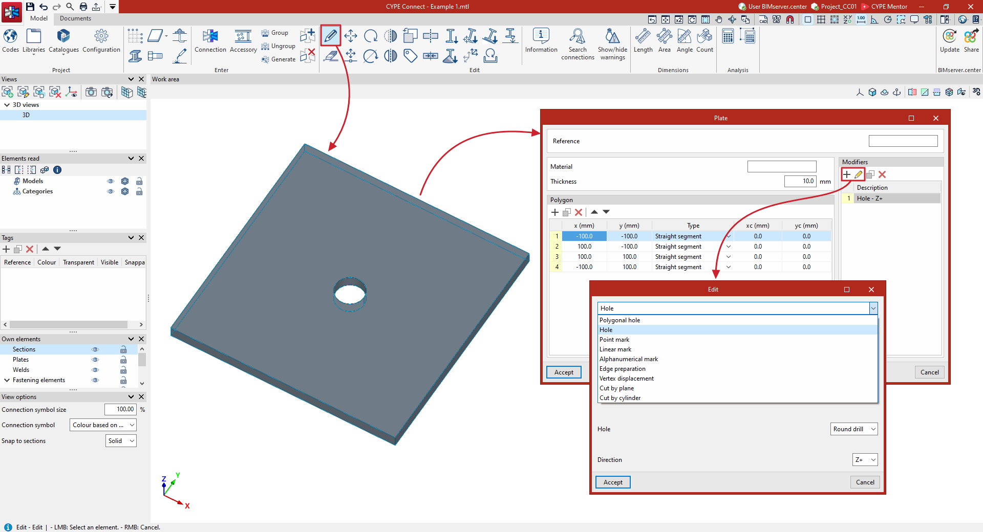
To insert plates into the general model of the structure, on the "Model" tab of the program interface, select the "Plate" option from the "Insert" group on the top toolbar.

Plate
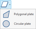
After clicking on the "Plate" option, a menu appears where you can choose whether to insert a "Polygonal plate" or a "Circular plate".
| Note: |
|---|
| This tool allows you to freely insert plates to complete the breakdown of the structure at specific points. However, if the aim is to model connections, including their analysis and compliance checks, it is advisable to use the "Joint" option instead, where it is also possible to insert plates using the specific operation. |
Polygonal plate
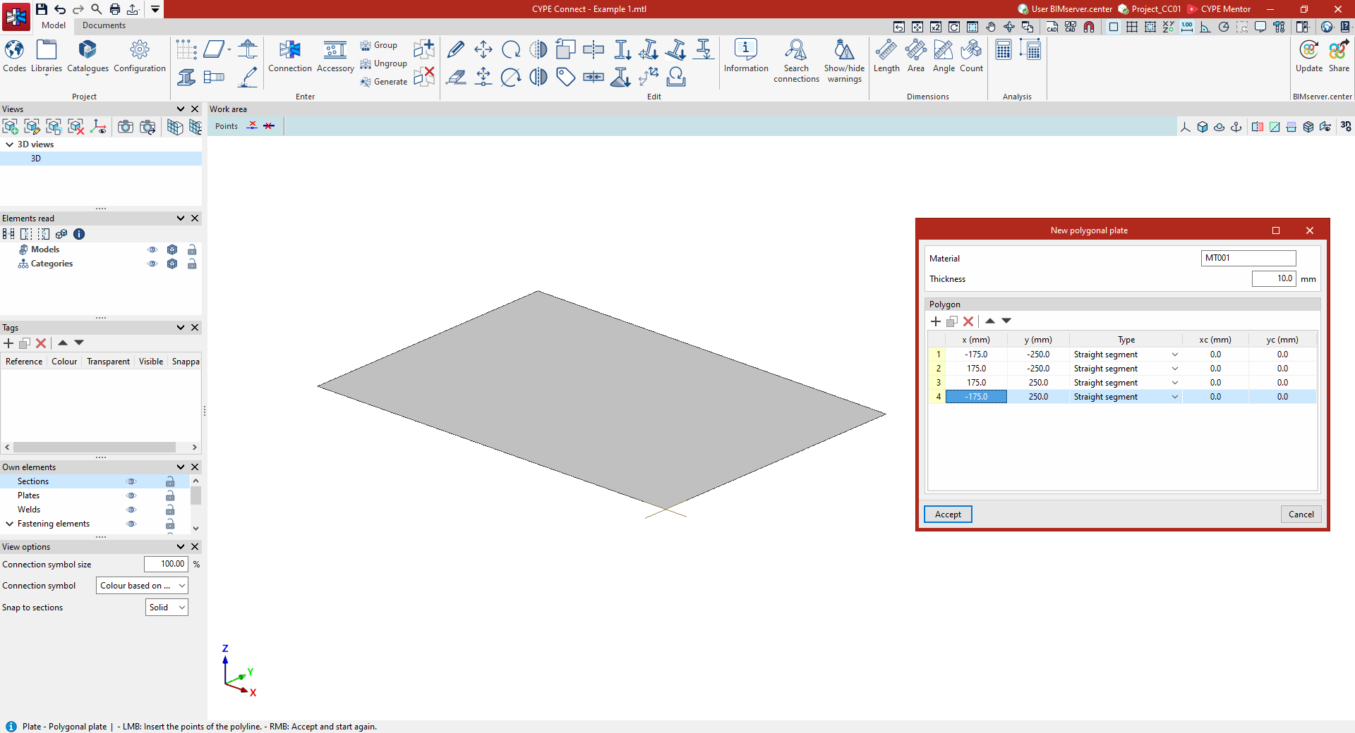
For a "Polygonal plate", you must select the points that define the perimeter of the polygon in the model using the left mouse button. Then, click the right mouse button.
This brings up the "New polygonal plate" window, where the "Material" and "Thickness" of the plate are defined. In the table below, you can review the "Polygon" data defining the plate, including the local "x" and "y" coordinates of the vertices, the "Type" of each segment – either a "Straight section" or a "Curved section" – and, if necessary, the coordinates of the centre of the curve, "xc" and "yc".
Next, click on "Accept" to confirm this information.
Circular plate
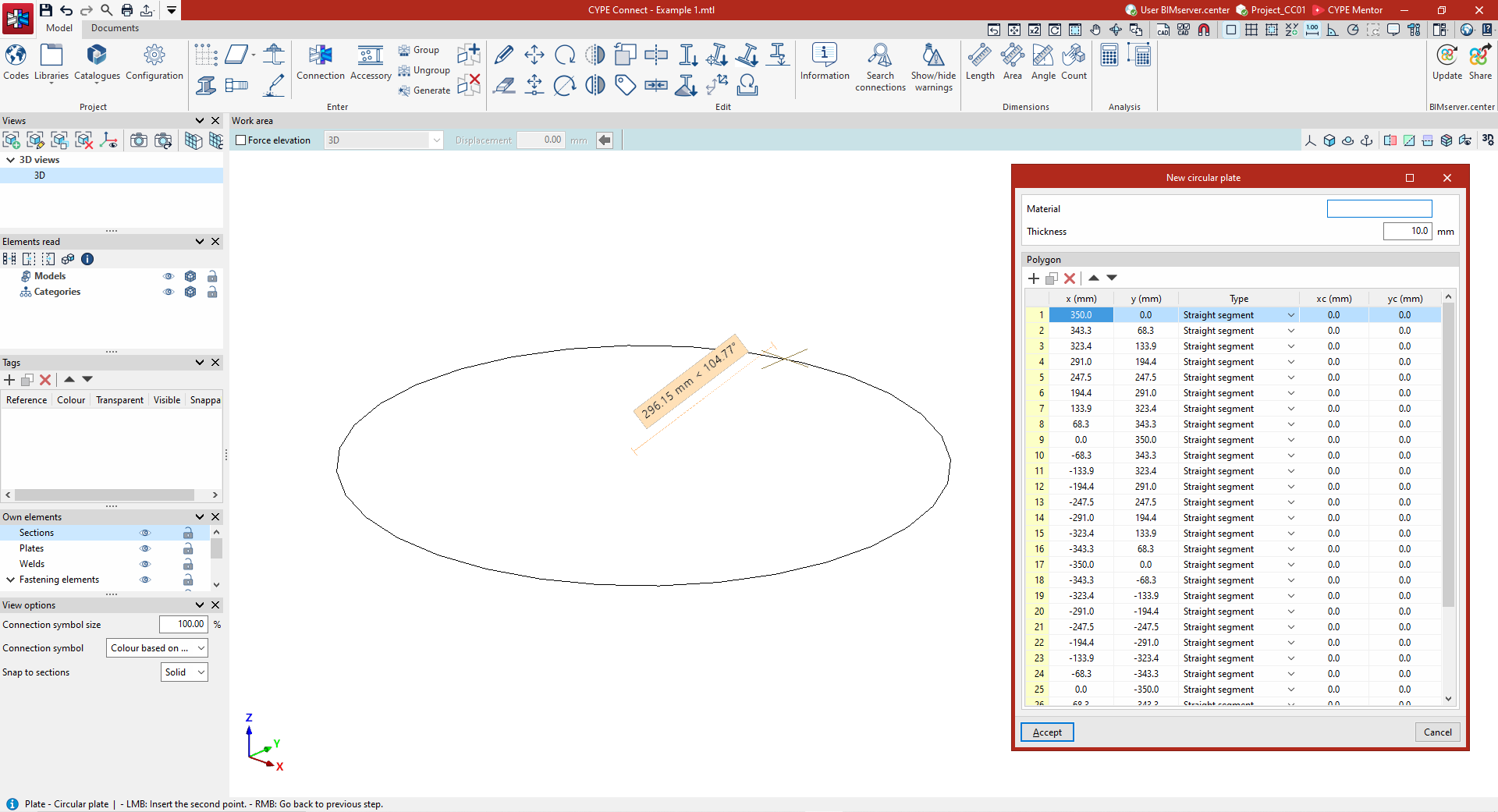
For a "Circular plate", you must use the left mouse button to select the centre and the radius of the circle that defines its perimeter on the model. Then, click the right mouse button.
This brings up the "New circular plate" window, with options equivalent to those mentioned above. In the table below, the program will have generated a regular "Polygon" made up of straight segments that approximates the circle entered.
Finally, click "Accept" to confirm this information.
Editing plates and entering modifiers
If required, use the "Edit" option in the "Edit" group on the top toolbar to modify or complete the definition of the plates.
After left-clicking on one of them, the "Plate" window opens, where you can enter its "Reference" and edit the details for the "Material", "Thickness" and "Polygon" of its outline.
Furthermore, in the table on the right, you can enter one or more "Modifiers" for the plate. After clicking "Add", a window opens where you can define the "New" modifier by selecting it from the drop-down menu.
The following options are included:
- Entering a "Polygonal hole"
- Entering a "Hole"
- Adding a “Point marker”, a “Line marker” or an “Alphanumeric marker”
- Defining an "Edge preparation", a "Vertex displacement", a "Cut by plane" or a "Cut by cylinder".
The program offers various options for adjusting the settings for each of these modifiers.
Finally, to finish editing the plate, click "Accept".