Editing tools in the "Model" tab
The tools for editing the general structure model are located in the "Edit" group on the top toolbar, within the "Model" tab of the program’s main interface:

 | Edit | Select an element in the model and edit its parametric properties. After clicking on the option, you can hover the pointer over the elements in the model; those that can be selected will be highlighted in blue. When you left-click on an element, the program will open the editing window. |
 | Delete | Delete one or more previously selected elements. After clicking on the option, select the elements one by one using the left mouse button or by dragging to select an area; the program will highlight them in orange. Right-click to delete them. |
 | Moving a group of elements | Move a group of elements. After clicking on the option, select the elements using the left mouse button and confirm the selection with the right mouse button. Then, use the left mouse button to mark two points that define the start and end of the displacement. |
 | Move | Move the point of a single element. After selecting this option, click on the element you wish to move, then click the left mouse button to select the point you wish to move. Next, click the left mouse button again to specify the new position of the selected point. |
 | Rotate | Rotate a group of elements. After clicking on the option, select the elements using the left mouse button and confirm the selection with the right mouse button. Next, mark the centre and angle of rotation by selecting two points with the left mouse button. The plane of rotation will follow the working plane defined in the view where the operation is being carried out. |
 | Rotate about an axis | Rotate elements about an axis. After clicking on the option, first select the elements using the left mouse button. After confirming with the right mouse button, mark two points to define the axis of rotation. Then, enter the "Rotation angle" and confirm by clicking on the green tick. |
 | Symmetry (move) | Move the selected elements symmetrically about a vertical plane defined by two points. To do this, after selecting the elements with the left mouse button and confirming with the right mouse button, select two points that define the plane of symmetry. |
 | Symmetry (copy) | Copy a selection of elements symmetrically with respect to a vertical plane defined by two points. To do this, select the elements using the left mouse button, confirm the selection with the right mouse button, and then mark two points that define the plane of symmetry. In this case, after the symmetry operation, the original elements remain in the model. |
 | Copy | Create copies of one or more elements. After selecting them with the left mouse button and confirming the selection by right-clicking, use the left mouse button to mark the start point and end point that define the distance the copy will be moved. You can left-click on further points in succession to generate more copies of the selected group of elements. |
 | Assign tags | Assign the tags from one element to another. |
 | Divide | Divide a bar into two parts at a specific point. To do this, after selecting the option, click on the section you want to divide. Then, mark the division point. We recommend enabling object snaps to help you position this point. |
 | Join | Combine two or more collinear sections into a single section. To do this, select the sections with the left mouse button, then click the right mouse button. |
 | Assign section | Assigns the cross-sectional properties of a specific bar – selected first – to another bar or group of bars selected subsequently. When you right-click, a window appears in which you can assign the "Type" and "Section" and, where applicable, its "Layout". |
 | Assign material | Assign a material to a beam or group of beams. To do this, select the desired sections and then right-click to open the window where you can assign the "Material" type to them. |
 | Assign insertion point | Once you have selected the section or group of sections, you can right-click and, in the window that appears, set the alignment point, the "Rotation" angle, the "Y displacement" and the "Z displacement" in local axes. |
 | Invert the direction of the X axis | Reverses the direction of the “local” X-axis for a selection of profiles. After selecting the profiles with the left mouse button, click the right mouse button. The programme will then swap the coordinates of the start and end points of each selected profile. |
 | Align section with the plane | Aligns a selection of profiles to a specified plane. After clicking on the option, select the profiles using the left mouse button and confirm the selection with the right mouse button. You must then click the left mouse button to select the alignment plane, which can be taken from the surfaces of other elements in the model. The programme will automatically apply a rotation angle to the specified profiles to align their local XY plane with the selected plane. |
 | Flip | Flip the selected sections about their longitudinal axis, without changing the coordinates of the start and end points of each section. To do this, after clicking on the option, select the section or sections to be flipped using the left mouse button, or define a selection area. You then confirm the operation using the right mouse button. |
 | Level section face with plane | Levels the face of the selected sections to a plane. After clicking on the option, select the section or sections you wish to move by left-clicking on the reference face of each one. Then confirm the selection by right-clicking. Finally, use the left mouse button to select the parallel face of another element, to which the reference face of the previously selected sections will be aligned. |
In addition, the program offers the following features in this section:

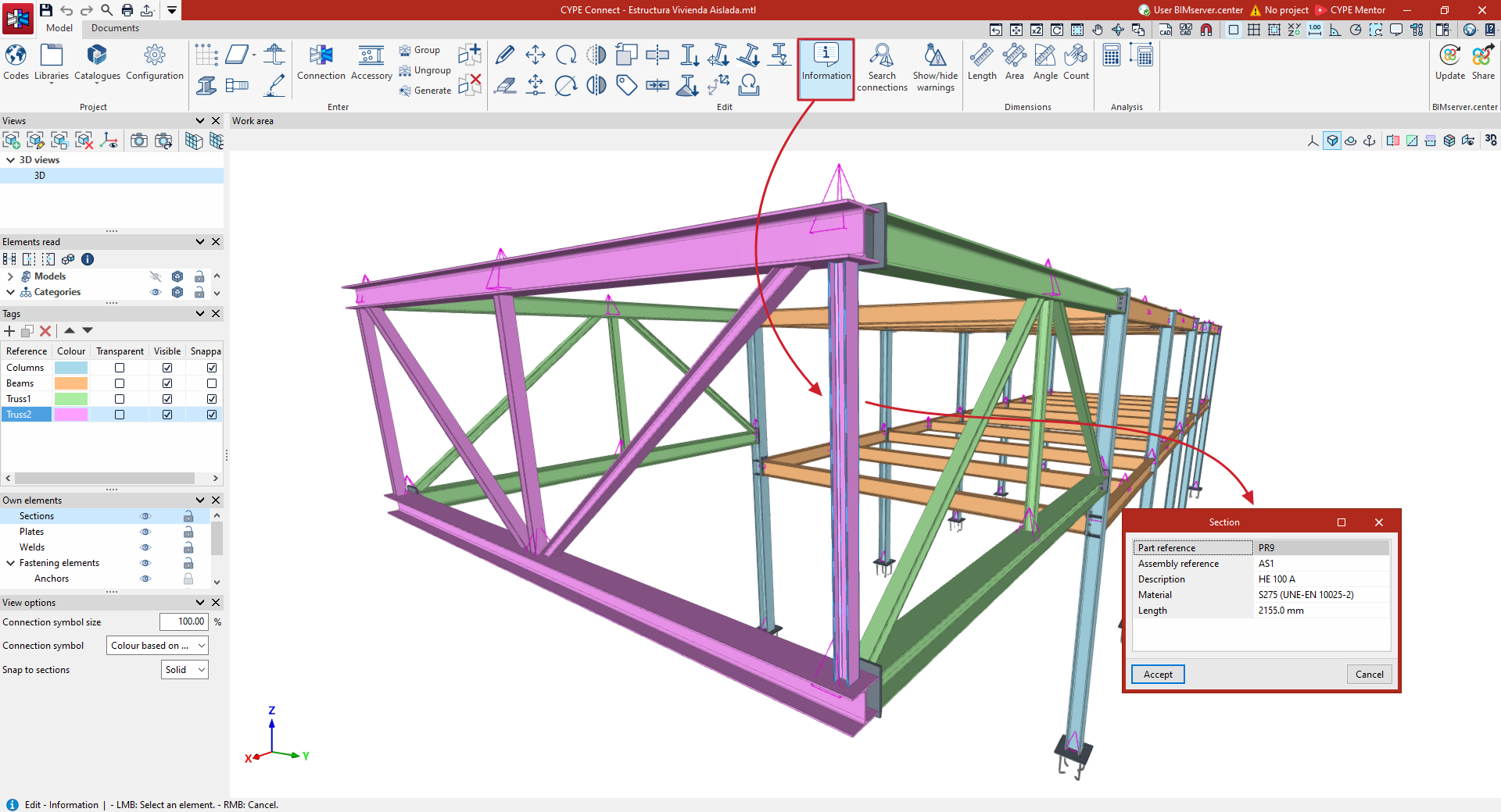
Information
This option allows you to view information about the selected elements in the model in a pop-up window.
For example, the sections show the "Part reference", the "Assembly reference", the "Description", the "Material" and the "Length".
Search for connections
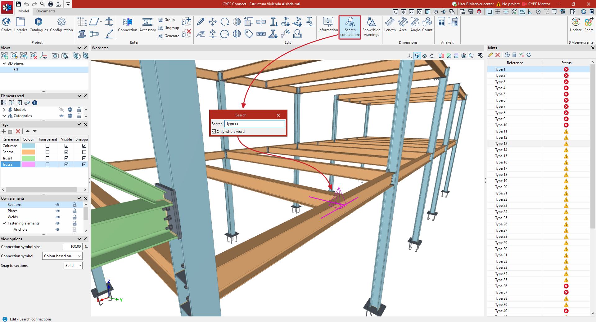
This option allows you to search for connections by entering part or all of their reference text.
To do this, when you run the tool, a panel appears where you can enter the reference number of the connection you wish to locate. Connections whose reference number matches the text entered either fully or partially will be highlighted in magenta, depending on whether the "Only whole word" option is enabled or not.
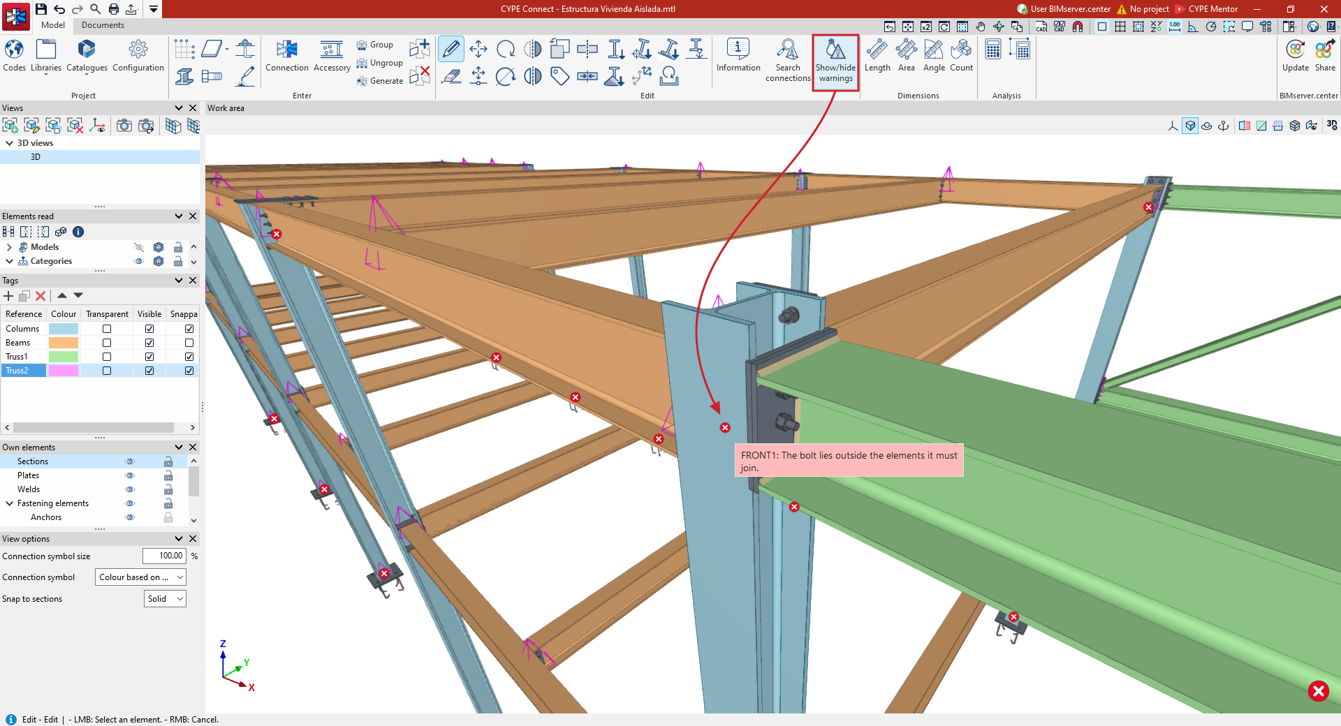
Show/hide notifications
This option allows you to show or hide the symbols indicating warnings or errors that have occurred in the model.
Errors that occur while defining a connection in the connection editor are indicated by a marker placed over the connection.