

"Model" tab interface
The CYPE Connect software’s user interface follows the same design principles as other CYPE tools. You have access to dockable and customisable windows, allowing you to tailor the workspace to the needs of your project.
At the top left of the screen, you will find two tabs:
- Model
- Documents
The "Template" tab is organised as follows:
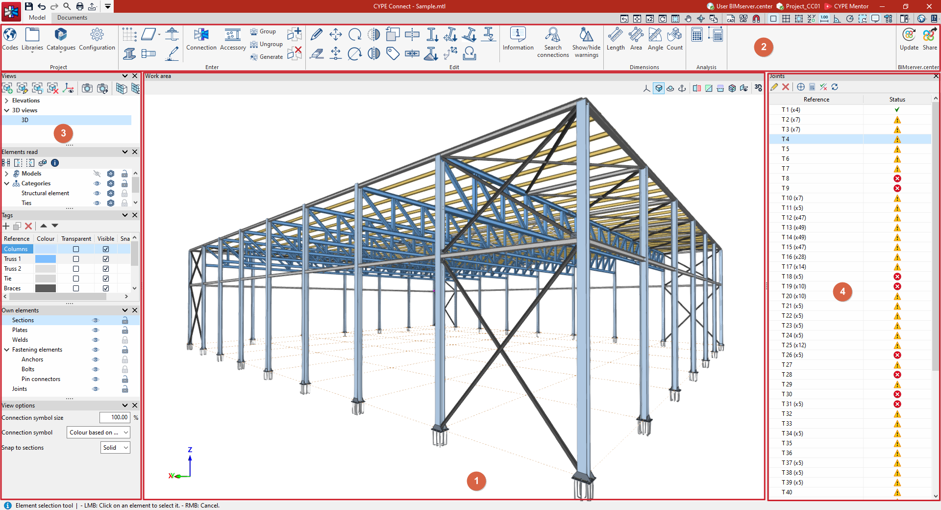
1. Work area (centre)
- Enter the project details.
- Change them.
- View them in 3D.
2. Main toolbar
- Change the general project settings (e.g. selecting the standard, managing element libraries).
- Insert the structural elements into the model (structural sections, plates, bolts, anchors, welds).
- Access the editing tools.
- Use the measurement tools on the model elements.
- Start the assembly group analysis.
- Link to and share the publication with a project on BIMserver.center.
3. Panels (left)
- Define the project views.
- Manage the visibility of read elements, tags and your own elements.
- Adjust the display settings.
4. List of assemblies (right)
- View the list of connections created in the model.
- For each connection, access its editing and analysis interface.
