

Dissipative elements in connections
Connections involving dissipative elements can be analysed. This allows for the design of connections in earthquake-resistant structures in which energy dissipation is achieved through the formation of plastic hinges, either in one of the connection elements or in the bars connected to it.
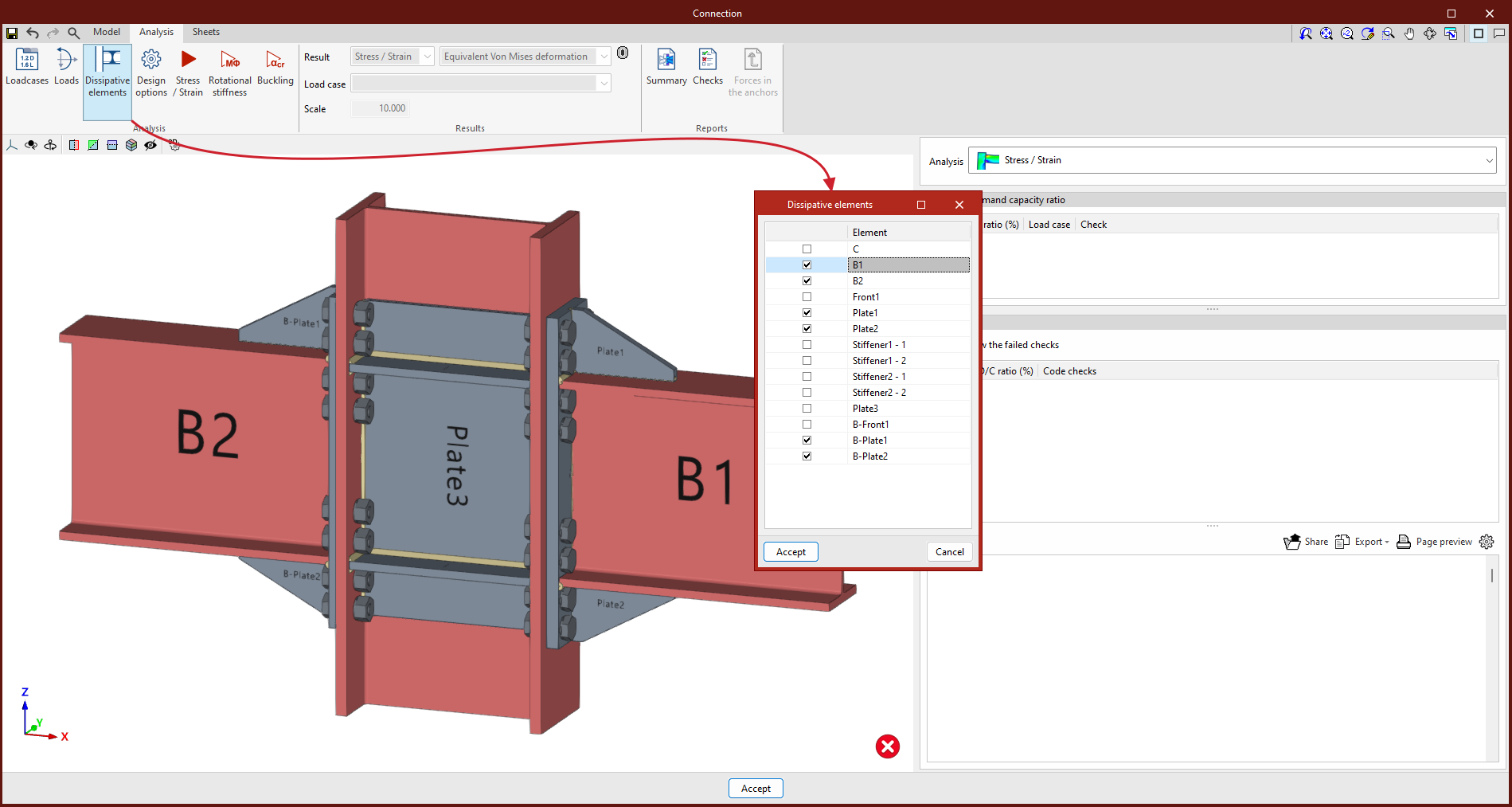
Selecting dissipation elements
In the "Analysis" tab, you can select "Dissipative elements" using the relevant tool in the "Analysis" group, which allows you to choose between sections and plates. To do this, tick the box in the first column of the window that appears when you click on this option.
The material properties of the dissipative elements are converted into "Load cases" labelled as "Capacity design", and the effects of material overstrength are taken into account.
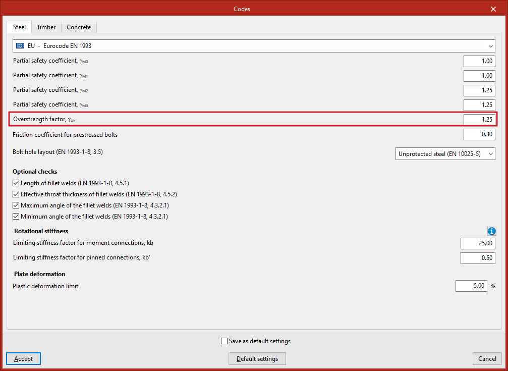
Entering overstrength factors
If the Eurocode or similar standards have been selected, the program requests the "Overstrength factor, 𝛾ov", which increases both the elastic limit and the ultimate limit of the dissipative elements.
This parameter can be configured in the "Steel" tab of the window that appears when you click on the "Codes" option, within the "Project" section of the "Model" tab on the program’s main interface.
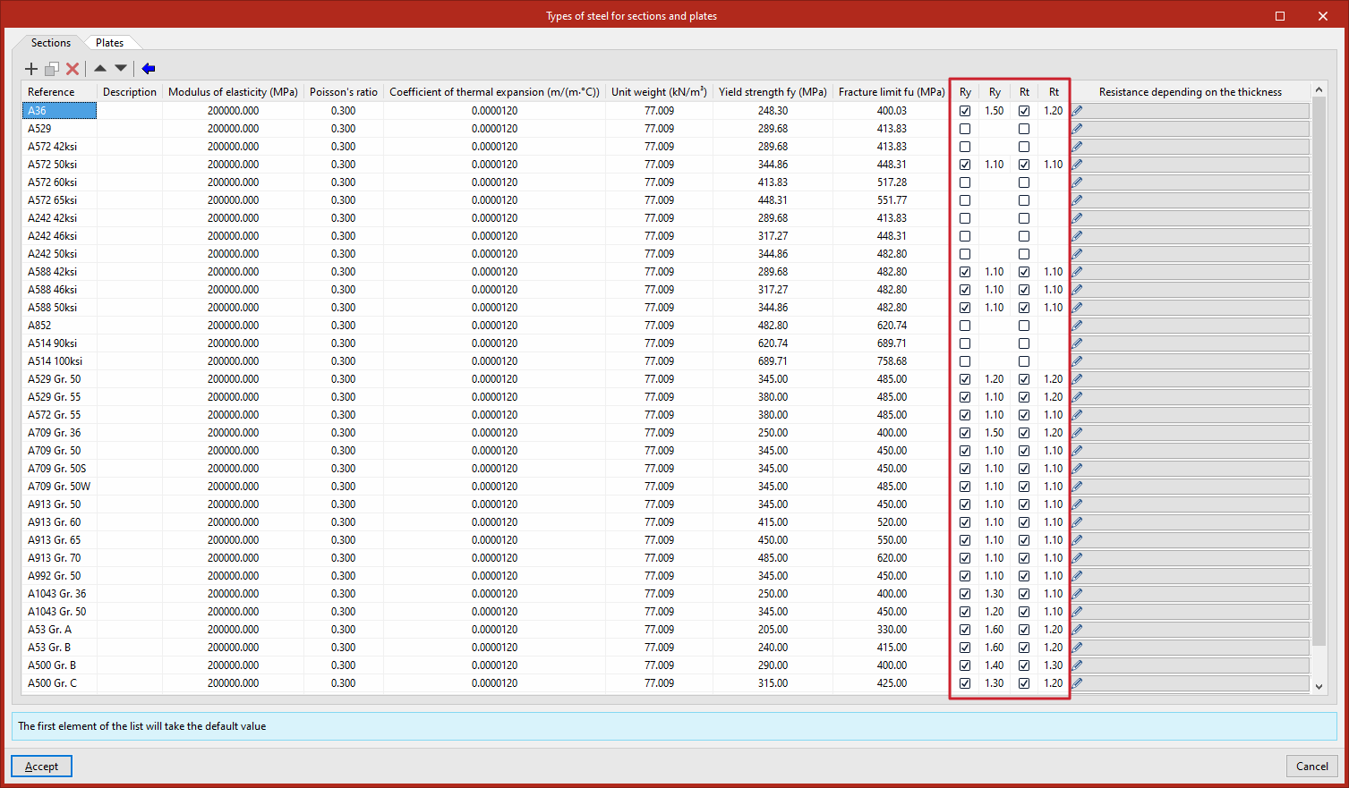
If American standards such as AISC360, NSR10, NTC-2023 and other similar standards have been selected, the program includes, within the library of steel section and plate types, the specific over-strength factors for each steel grade, "Ry" and "Rt":
- Ry
Ratio of the expected creep resistance to the specified minimum creep resistance. - Rt
The ratio of the expected tensile strength to the specified minimum tensile strength.
The "Steel sections and sheets" library can be accessed from the "Project" section of the "Model" tab on the program's main interface by clicking on the "Libraries" menu and then selecting “Elements and materials”.
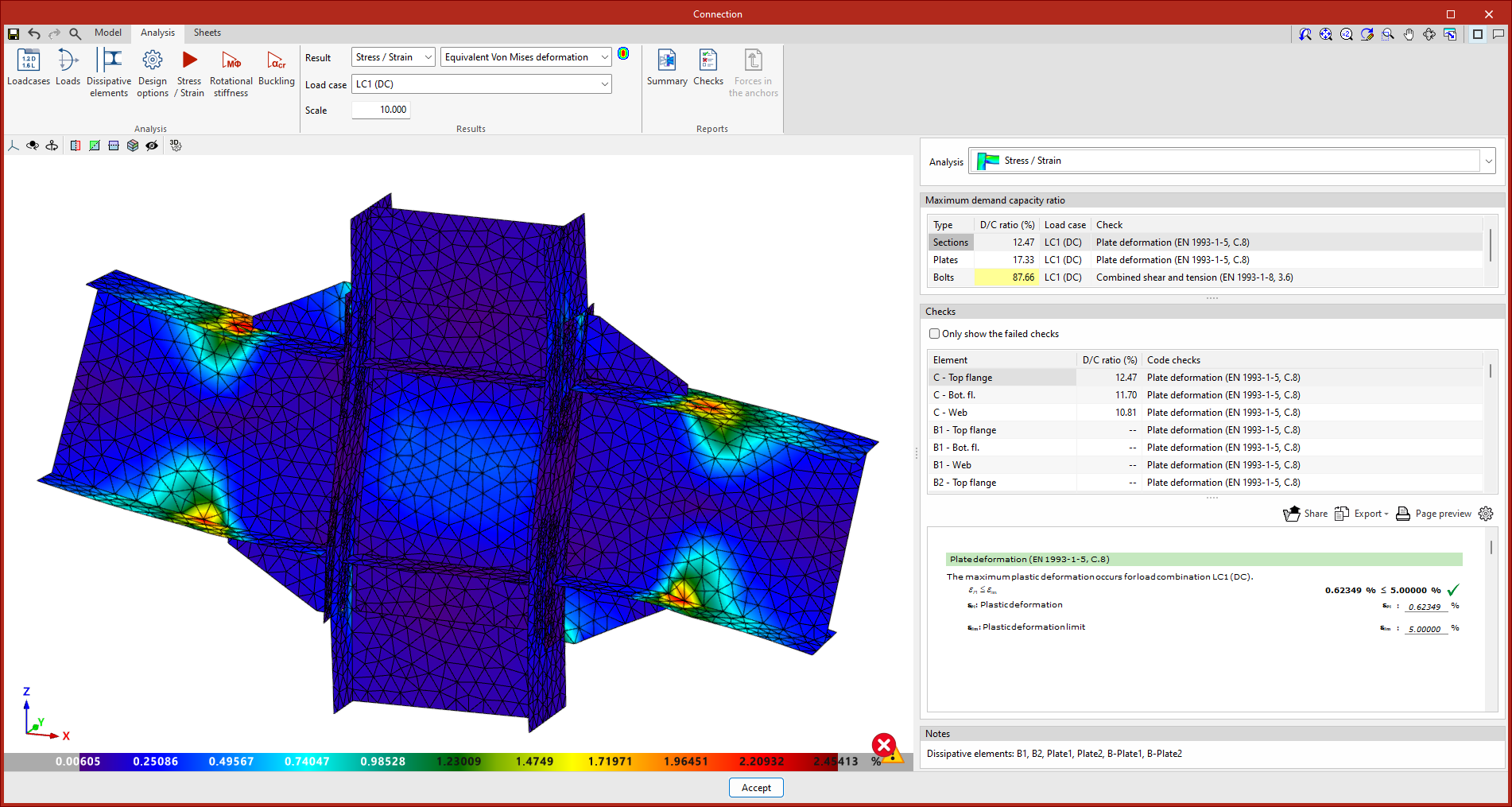
Selecting load cases to be analysed using capacity-based design criteria
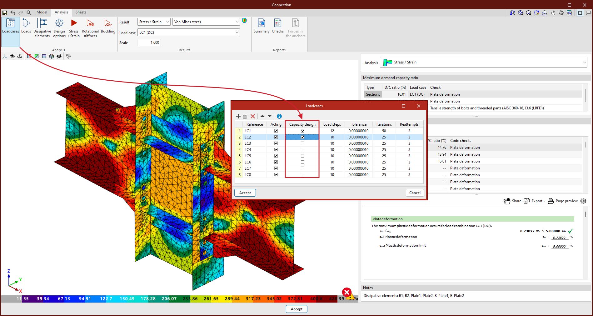
To analyse the connection whilst taking into account the excess strength in dissipative elements, you must not only select the dissipative elements but also select the "Capacity design" load cases from the "Load cases" list, which can be accessed via the relevant option in the "Analysis" group.
Design and results
This makes it possible to design connections so that the connection capacity is greater than that of the dissipative element, taking into account the safety factor. In such cases, the dissipative elements will undergo significant plastic deformation, which hinders the convergence of the model. Therefore, another relevant parameter for dissipative elements is the slope of the plastic region.
The constitutive law for plates and sections follows a bilinear model, where the slope of the plastic region is tan⁻¹ (E/1000). In dissipative elements, in addition to incorporating the over-strength coefficient as a multiplier of the elastic limit, the slope of the plastic region is adjusted. In these elements, for a deformation of 5 per cent, the stress will reach the material’s elastic limit, amplified by the over-strength coefficient (𝛾ov or Ry, depending on the standard applied) and by the strength reserve coefficient due to strain hardening, which is equal to 1.1. This slope, which is greater than tan⁻¹ (E/1000), helps to improve the convergence of the analysis.
