Defining loadcases in the connection editor
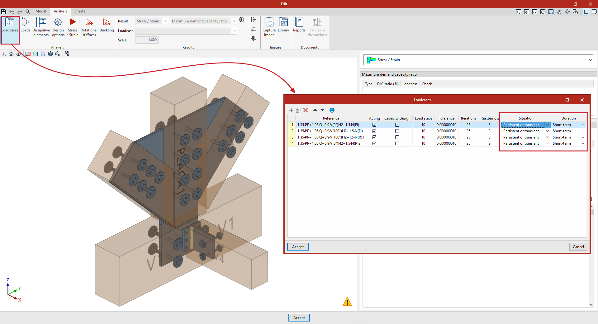
To configure loadcases in the program, use the "Loadcases" option on the top toolbar of the "Analysis" tab within the connection editor.

Loadcases
The window that appears when you click this option is used to define the loadcases that can be taken into account in the connection analysis.
Generating or entering loadcases
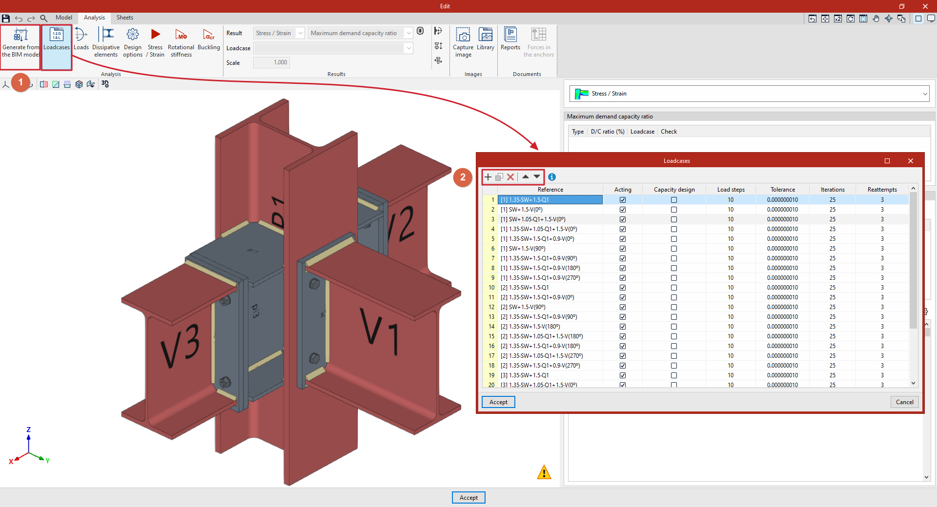
Loadcases may have been generated automatically using the "Generate from the BIM model" option (1), located on the top toolbar of the "Analysis" tab interface.
You can also edit or enter them manually. In that case, you use the buttons at the top of the table (2), which allow you to "Add", "Copy", "Delete" and move loadcases within the list.
Defining loadcases
The following parameters are defined for each loadcase:
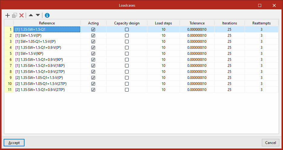
- First, enter the "Reference" for the loadcase.
- Next, you indicate whether or not the loadcase is "Acting" in the analysis by ticking the relevant box.
- To analyse the connection taking into account the safety factor in dissipative elements, tick the "Capacity design" box for loadcases of this type in the list (in addition, "Dissipative elements" must be selected using the corresponding option on the top toolbar of the "Analysis" tab interface). The material properties of the dissipative elements are adjusted for the selected loadcases, taking into account the effects of the material’s over-resistance.
On the right are the configuration parameters for the non-linear analysis of the connection carried out by the program using the OpenSees engine. Material, geometric and contact non-linearities can cause changes to the stiffness matrix. For this reason, the analysis process is incremental and iterative:
- Loadsteps
The loads applied in each load case are divided by the number of "Load steps" indicated in this column, and are applied incrementally at each step until 100 per cent of the loads is reached.
For example, if a load of 100 kilonewtons is applied and 5 steps are defined, each load step will add a further 20 kilonewtons until the total reaches 100.
The values in the following columns, "Tolerance" and "Iterations", are associated with each load step.
- Tolerance
In this column, you must enter the permitted "Tolerance" for determining that convergence has been achieved.
The convergence criterion used to terminate the iterative process at each loading step is the energy error.
When the change in energy between one iteration and the previous one is less than the defined tolerance, the program considers that equilibrium has been reached at that loading step and moves on to the next one.
- Iterations
This column shows the maximum number of "Iterations" to be carried out at each load step.
- Retry attempts
If equilibrium is not reached at any step within the maximum number of iterations entered, the analysis is restarted by doubling the number of load steps.
If equilibrium is still not reached, this process is repeated and is terminated if the maximum number of "Retry attempts" entered in this column is reached.
The default values in the program are considered optimal for achieving good results within a reasonable analysis time.
Finally, if the connection includes timber sections, the "Condition" and "Duration" for each loadcase are also selected from the relevant drop-down menus.