Viewing the results of the rotational stiffness analysis in the connection editor
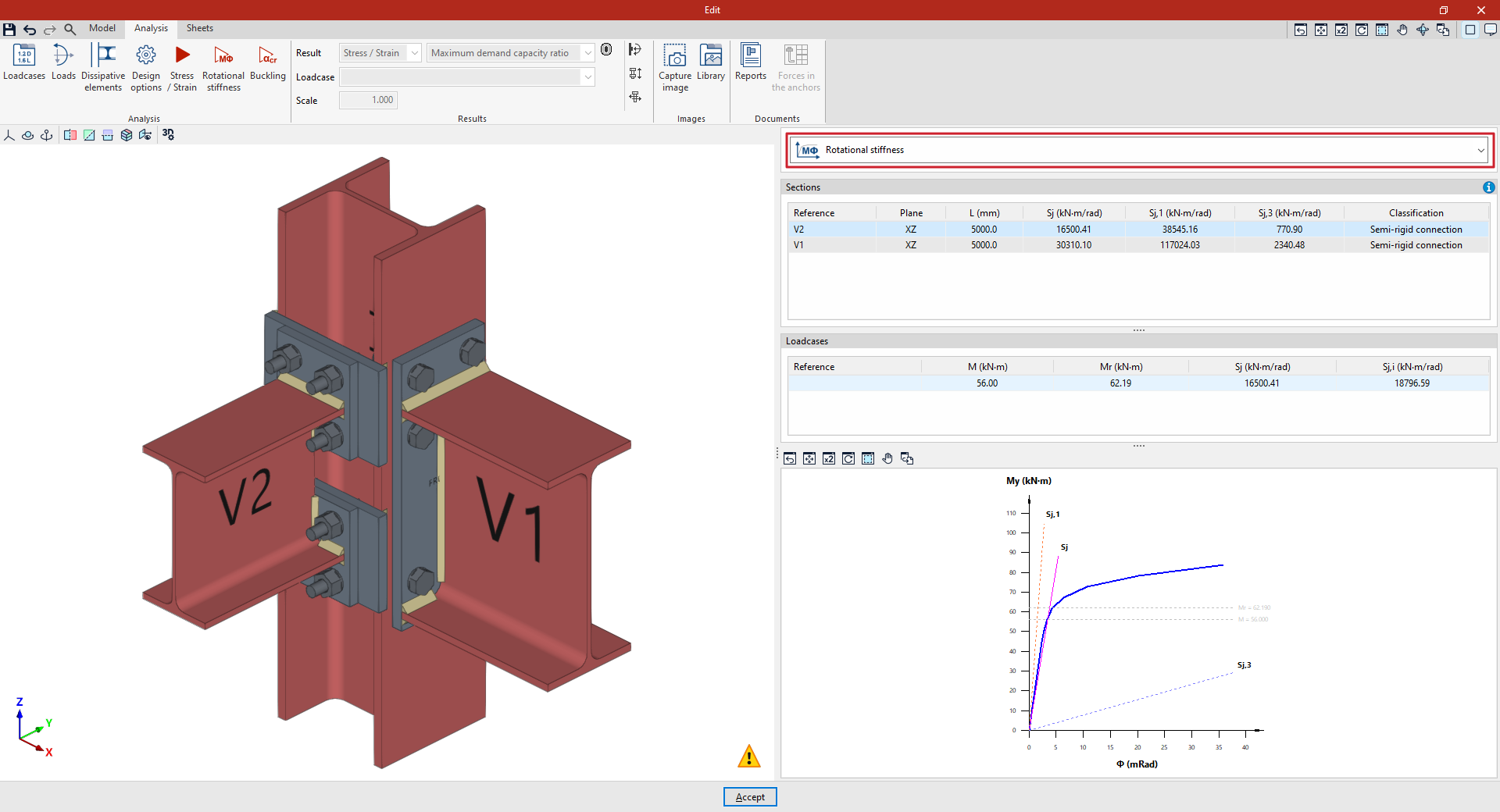
The results of the rotational stiffness analysis are displayed on the right-hand side of the "Analysis" tab, within the connection editor.
From the drop-down menu at the top, you can select the type of results to be displayed. When you select "Rotational stiffness" from this drop-down menu, the program displays two tables and the moment-rotation diagram:
"Sections" table
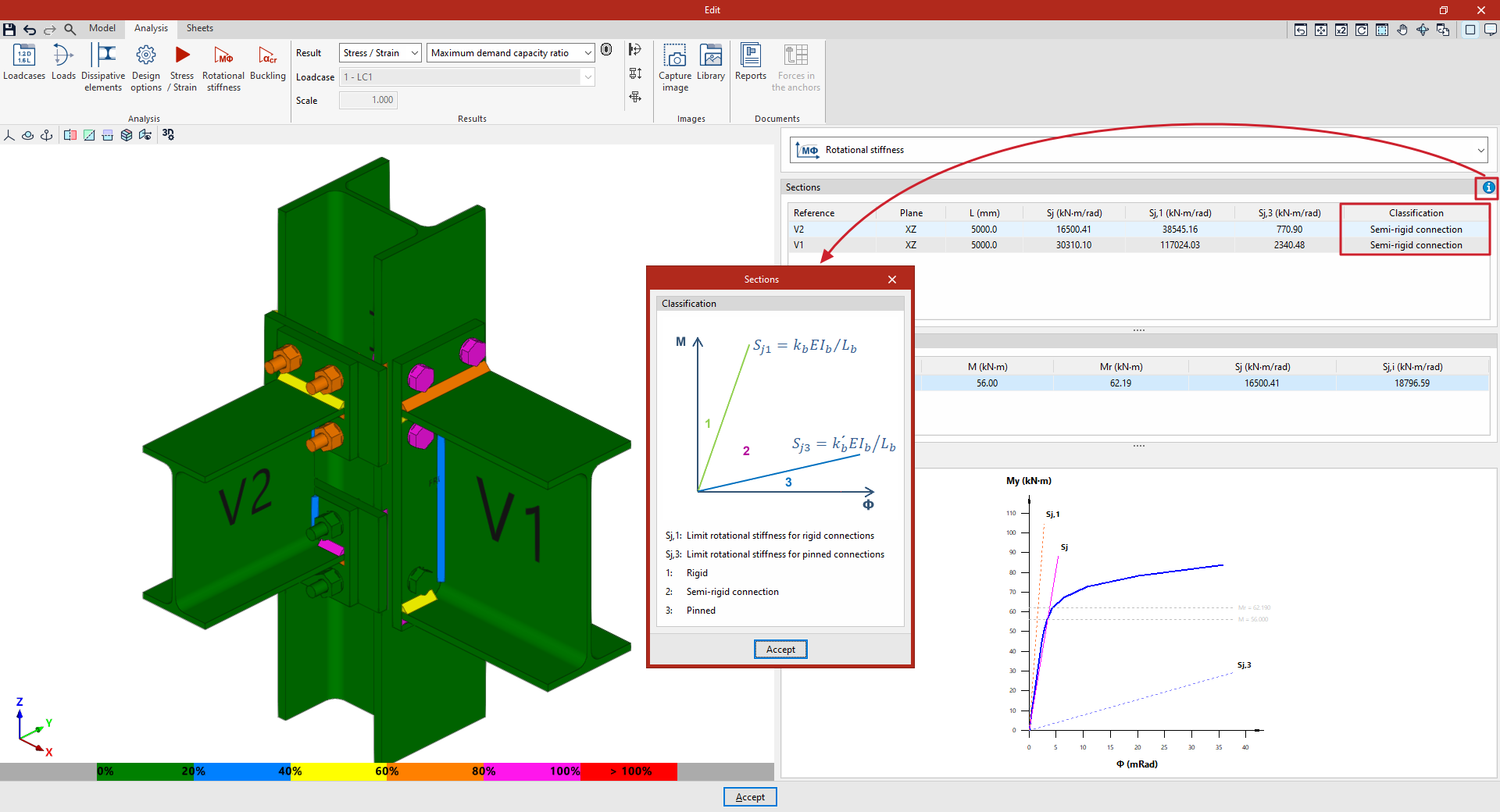
The first table shows all the analysed bars with their "Reference", "Plane", "Length", secant stiffness ("Sj"), the limit rotational stiffness for rigid connections ("S,j1"), the limit rotational stiffness for pinned connections ("Sj,3") and the classification of the connection in each plane ("Rigid", "Semi-rigid" or "Pinned").
To classify a connection as rigid, semi-rigid or hinged, the limit stiffness values for rigid and hinged connections must first be established. Depending on the selected steel standard, either the initial stiffness or the secant stiffness will be compared with these limits.
"Loadcases" table
This table shows the load cases calculated for the selected member. Each load case indicates the applied moment ("M"), the resisting moment ("Mr"), the secant stiffness ("Sj") and the initial stiffness ("Sj,i").
Moment-rotation (M-Φ) graph
The graph shows the moment-rotation curve, the applied moment for the selected loadcase (M), the resisting moment (Mr), the secant stiffness (Sj), the limit stiffness for rigid connections (Sj,1) and the limit stiffness for hinged connections (Sj,3).
The diagram, which can be accessed via the help button in the top right-hand corner, shows the "Classification" of the connection as "Rigid" (1), "Semi-rigid" (2) or "Hinged" (3) in the M-Φ plane, based on the definition of the "Limit rotational stiffness for rigid joints", Sj1=kbEIb/Lb, and the "Limit rotational stiffness for hinged joints", Sj3=k'bEIb/Lb.