

"Trim section" option
The "Trim section" option is used to trim the selected section based on the dimensions entered. The type of trim can also be defined: straight, with a radius or with a drill hole.

Inserting and defining section trims
To insert the trimming, click on the "Trim section" option in the top toolbar.
Then, in the first drop-down menu, select the "Section" to be trimmed from those available.
Next, indicate the "Position" of the trimming, which can be at the "Top" or "Bottom" of the section.
Under "Type of trim", specify whether it is "Straight", "With chord radius", or "With drill hole":
- In all three cases, the “X” and “Y” dimensions of the cut-out must be specified in the units shown.
- When using cut-outs "With chord radius" or "With hole", the "Chord radius" or the "Hole diameter" is also specified, respectively.
- The image below is provided as an aid to understand the reference system for these dimensions. All of them refer to the envelope of the section, that is, its original geometry prior to the application of adjustments.
- The "Display options" can be used to make the position of the envelope visible in the joint view. To do this, the "Sections" are shown as transparent by clicking in the cell of the "Drawing" column, and the display of the "Envelope" is activated on the right. After clicking "Accept", the envelopes of the sections are displayed in grey.
Example
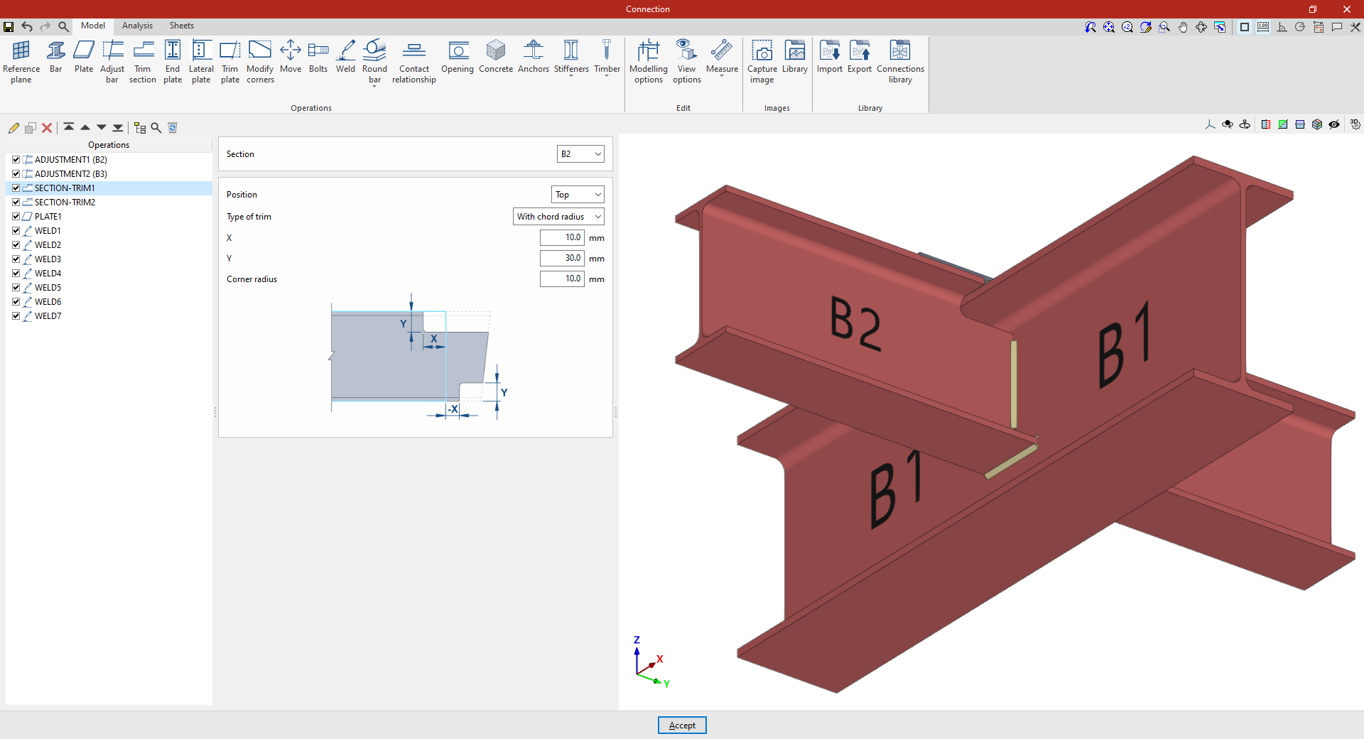
In the example shown here, corresponding to a connection between beams, adjustments have already been made to the sections of beams B2 and B3, which are perpendicular to beam B1.
Next, the necessary trims are made to avoid clashes identified by the program between the beam plates:
- In the first trim, one of the secondary beams, B2, is selected. The cut position is "Top", as the cut is to be made at the top of the section. A "Radius match" cut is used, with an X dimension of 10 millimetres, a Y dimension of 30 millimetres and a radius of 10 millimetres.
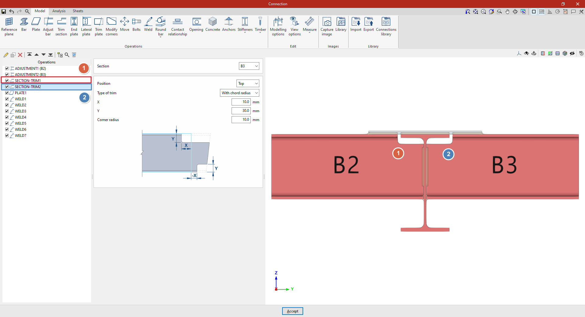
- To define the second trim, apply this operation to the other beam by selecting the first one and using the “Copy” option available at the top of the table on the left. In this new operation, in the "Section", beam B3 is selected, with the rest of the parameters remaining the same.
From this point onwards, the rest of the operations necessary to complete the joint model must be added before the "Analysis" of the connection can be performed.