
"Timber" functions: bolts
The "Timber" function is used to insert fasteners into timber bars.

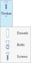
The fasteners available for timber include dowels, bolts and screws.
| Note: |
|---|
| This feature is only available in CYPE Connect. |
Inserting bolts
To insert dowels, open the “Timber” menu in the top toolbar and click on the “Bolts” option.
| Example: |
|---|
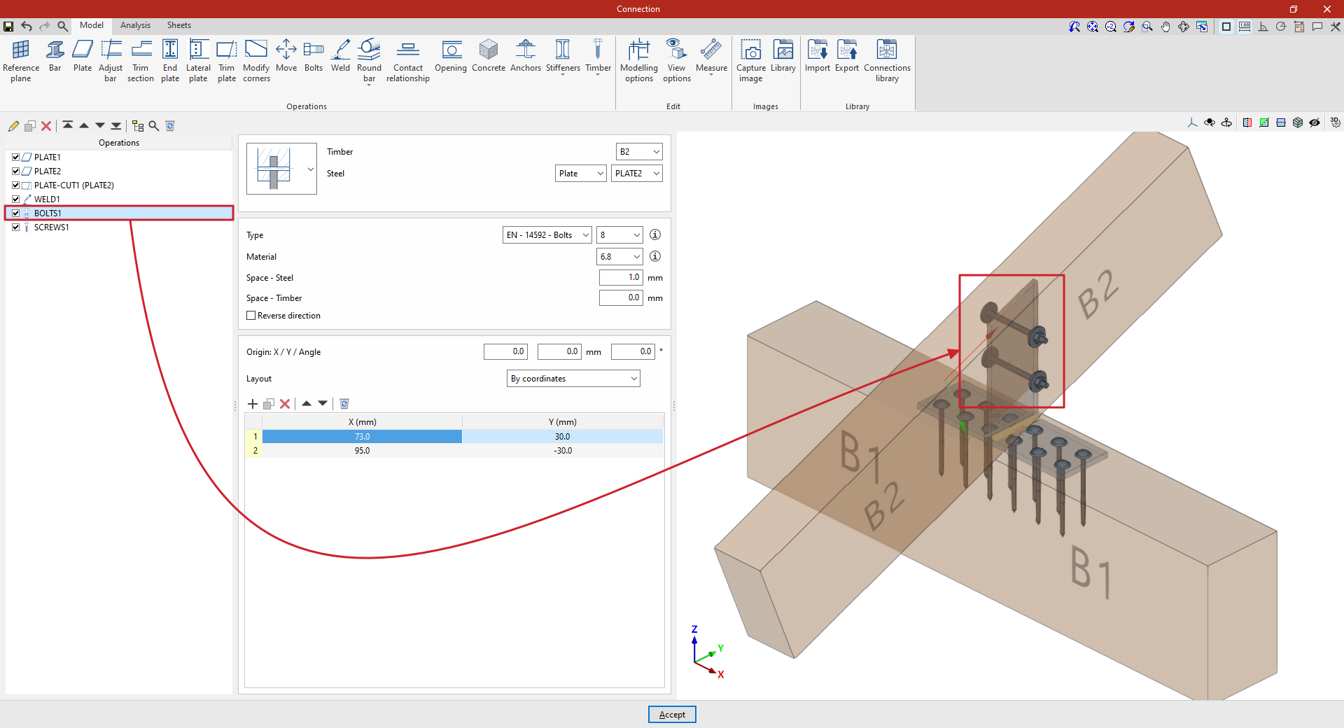
| In this example, the aim is to create a connection between two timber bars. First, a plate has been placed on the main beam B1. Next, a second plate has been added, positioned perpendicular to and welded to the first. Finally, bolts are inserted to create the connection between this plate and the secondary beam B2. |
Selecting the parts
In the first drop-down menu, you select whether the bolt connects a steel element and a timber element, two steel elements and an intermediate timber element, a single timber element and an intermediate steel element (as in this case), or two different timber elements and an intermediate steel element.
Next, on the right-hand side, select the “Timber” component and the “Steel” element from those available, whether a “Section” or a “Plate”. In this case, select beam B2 and plate 2.
Bolt configuration
Next, you need to specify the “Type” of bolt. Using the drop-down menus on the right, you can select the “Series” and “Diameter” from the available options.
After clicking “Accept”, you can click the button displaying the series name and diameter to modify these specifications, if required.
The button on the right allows you to view the following information:
- Firstly, the bolt’s "Series", "Nominal diameter", "Diameter of the thread", "Head diameter" and "Head thickness".
- The table then shows values indicating the “Length” of the bolt and the “Length of the threaded part”.
- The parameters for the “Nut” and the washers used in wooden and steel components (“Washer – Timber” and “Washer - Steel”), including the “Series” and “Nominal diameter” references, as well as the “Outer diameter”, “Inner diameter” and “Thickness” values for each component.
- It also specifies whether a “Locknut” is required on the bolt.
The following section specifies the bolt’s “Material”. Similarly, by clicking the button on the right, you can view the material’s properties, such as its “Reference”, “Description”, “Modulus of elasticity”, “Yield strength” and “Fracture limit”.
Later on, the space between the bolt and the steel component (“Space – Steel”) and the space between the bolt and the timber element (“Space – Timber”) are defined.
Finally, you can tick the last box to “Reverse the direction” of the bolt.
Positioning the bolts
Below is a table showing the number and position of the bolts.
- You must define the local X and Y coordinates and the angle of the positioning origin for the bolts on the plate or bar by entering this data in the "Origin: X / Y / Angle" fields.
- Below, it is indicated whether the "Layout" of the bolts on the plate or bar is:
- "By coordinates",
- By "Rows and columns",
- By "Rows and columns per flange" (in front plates on rolled I sections),
- "Perimeter" on the sheet metal,
- Or "Radial".
| More information: |
|---|
| More information on these layout options can be found via the following link. |
From this point onwards, the remaining operations required to complete the connection model must be added before the “Analysis” can be carried out.