
Defining FRP reinforcement
In the "FRP" section, accessible from the top of the interface, the FRP reinforcements in the analysed member are defined.
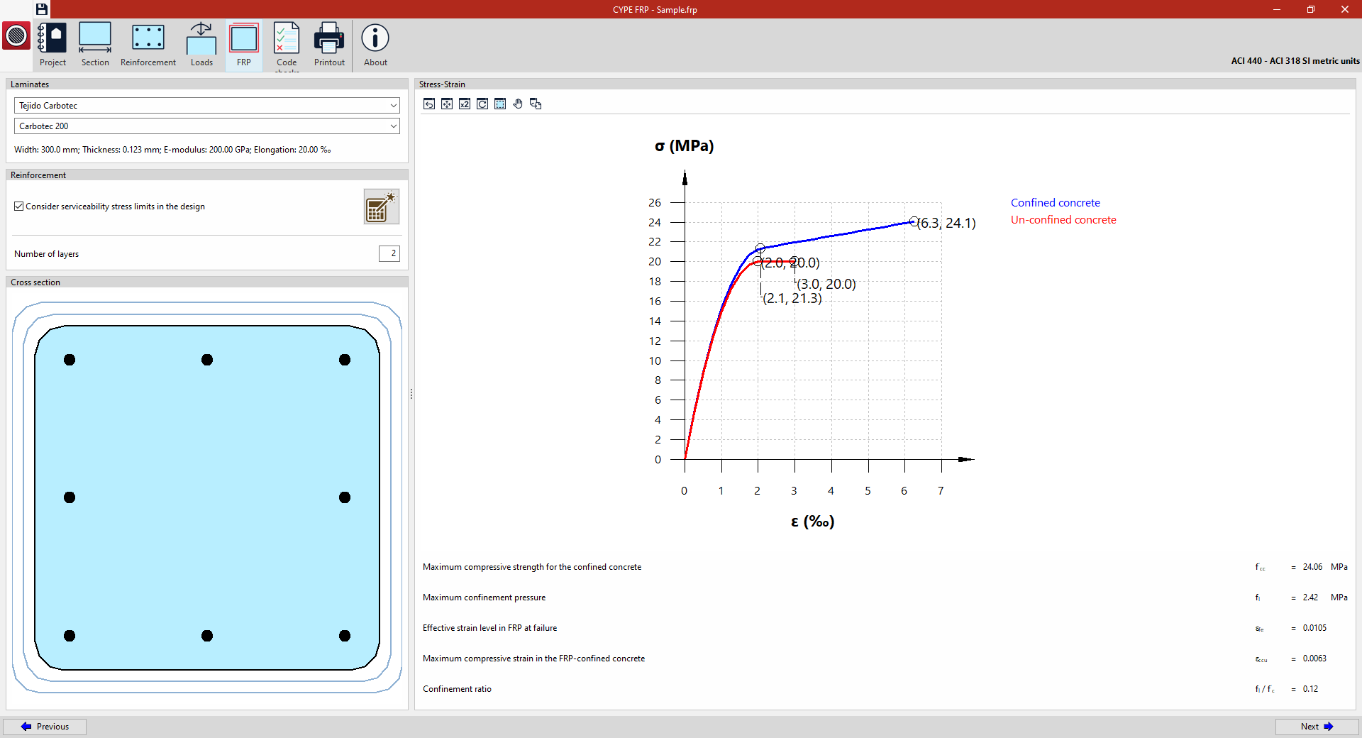
Example: FRP reinforcement of a column (analysis in accordance with ACI 440 – ACI 318)
The following details are defined in the "FRP" section:
- In the "Laminates" section, the specific series and product from the selected manufacturer are chosen when creating the project. The program displays the properties of the selected product, such as "Width", "Thickness", "E-Modulus" and "Elongation".
- In the "Reinforcement" section, you can either enter the "Number of layers" of FRP reinforcement manually or click the button provided to automatically carry out the "Calculation of the necessary number of FRP laminates". You can also "Consider serviceability stress limits in the design" by ticking the relevant box.
- The bottom right-hand corner shows the "Cross-section" of the element, including a view of the FRP reinforcement layers.
- On the right, a "Stress-Strain" diagram of the cross-section is shown, with two graphs corresponding to "Unconfined concrete" and "Confined concrete", indicating the number of layers of the selected product entered.
At the bottom, relevant parameters are shown, such as the "Maximum compressive strength for the confined concrete", the "Maximum confinement pressure", the "Effective strain level in FRP at failure", the "Maximum compressive strain in FRP-confined concrete", and the "Confinement ratio".
Once the dimensions of the FRP reinforcement have been analysed, the program enables the options that let you view the "Check" of the cross-section on screen and to "Print" the reports.