
Introduction
CYPE FRP is a program used to design and analyse FRP (Fibre-Reinforced Polymer, including carbon fibre laminates) reinforcement in reinforced concrete sections.
The program allows users to design, size and check flexural and shear strengthening solutions for beams, as well as column strengthening through FRP confinement.
To do this, download the manufacturers’ catalogues for the required FRP reinforcements and select a standard from those available, such as ACI 440 or TR55 (Technical Report 55). Next, define the cross-section and reinforcement of the structural member, as well as the loads acting upon it.
The program checks and verifies whether the section complies without reinforcement and, where necessary, allows the required FRP reinforcement to be defined and dimensioned.
Finally, the software provides detailed reports covering the design criteria and codes and standards applied, the calculation assumptions, the FRP strengthening solutions specified, the load combinations considered and the results obtained.
Starting and creating a new project
Language selection
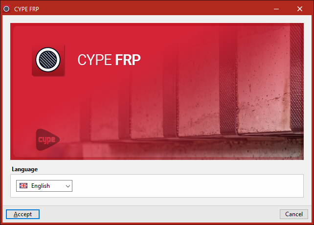
When you launch the app, you must first select the "Language" in which the program interface and the results will be displayed.
New job
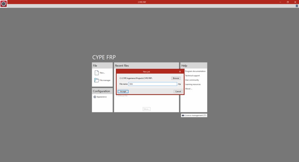
Once you have accepted, the initial interface that is the same as in other CYPE programs opens. When you click on "New", you can create a "New job". In the window that appears, enter the "File name".
The extension of the main file associated with the job is shown on the right; in this case, .frp.
You can change the folder where the work will be saved by clicking the "Browse" button.
Project parameters
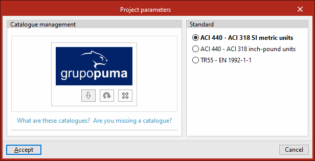
This opens the "Project parameters" window.
Here, in the "Catalogue management" section, you should download the manufacturer’s catalogues you wish to use from those available in the Open BIM Database.
On the right, in the "Standard" section, select one of the available standards (and, where applicable, the system of units):
- ACI 440 – ACI 318 SI metric units
- ACI 440 – ACI 318 inch-pound units
- TR55 - EN 1992-1-1
This will load and open the program with these settings. If you wish to use different settings, you will need to create a new project.
Project settings
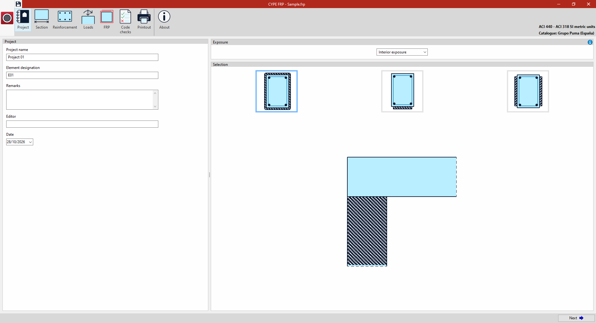
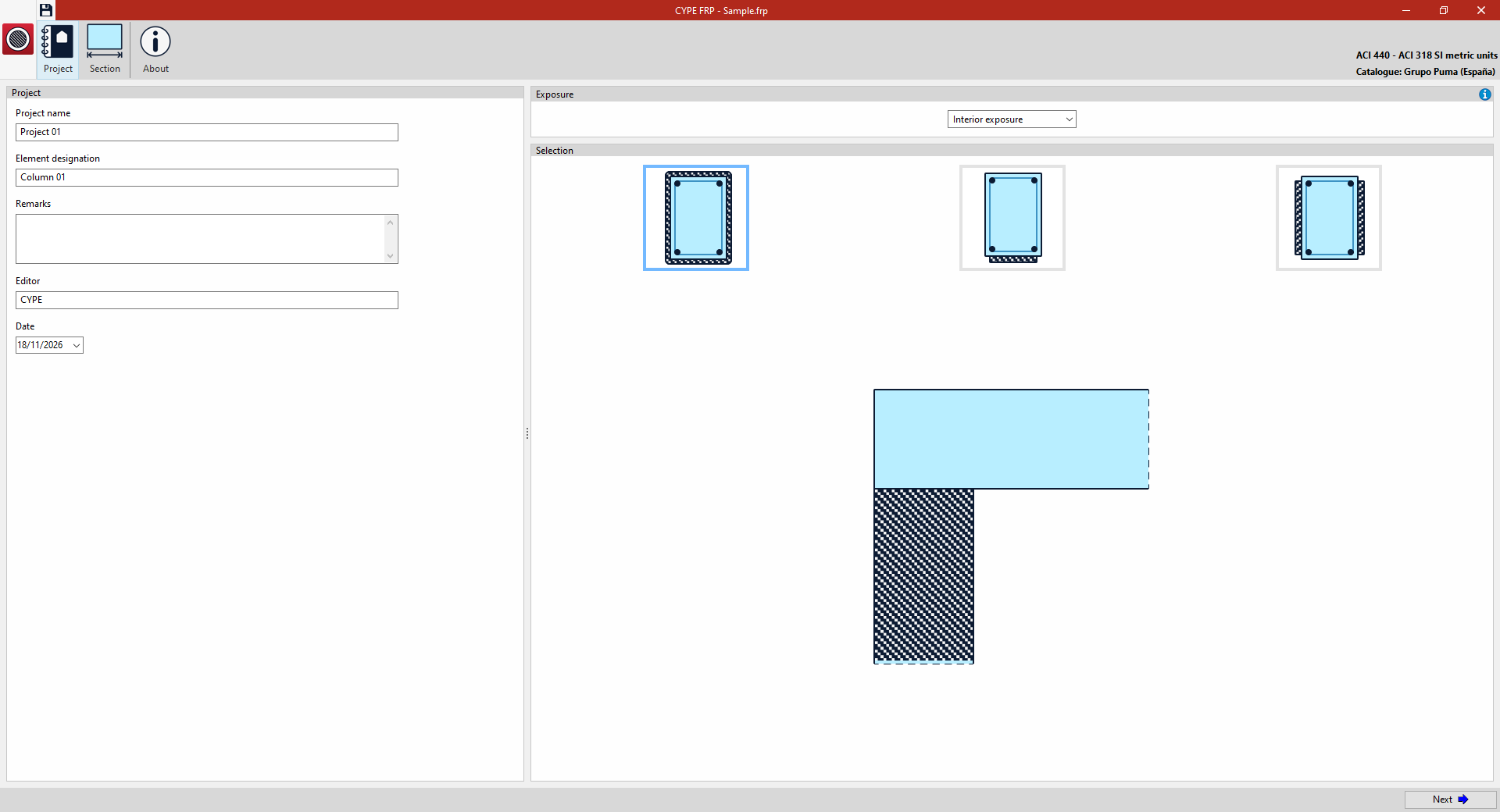
After launching and opening the program with the desired settings, the following must be defined in the "Project" section:
- On the left, the "Project" parameters, including the "Project name", the "Name of the item" to be analysed, any "Notes" to be included, the ‘Editor’ reference and the "Date" of the work.
- f the ACI 440–ACI 318 standards are used, the long-term environmental "Exposure" of the member must be selected in the corresponding field on the right-hand side. This must be taken into account as an initial design assumption, as it will affect the determination of the safety factor applied in the design equations. The available options are:
- Interior exposure
- Exterior exposure
- Aggressive environment
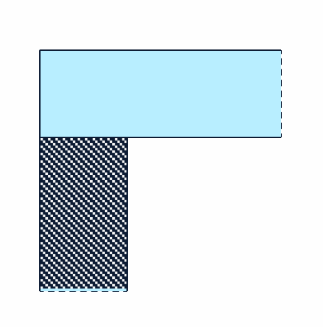
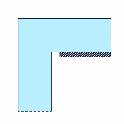
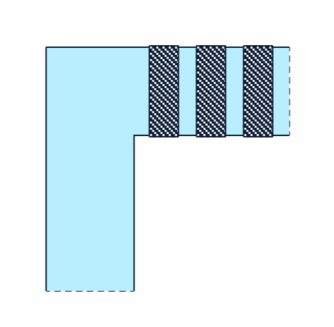
- Finally, the case to be analysed is 'selected' from those available. These are as follows:
- Column strengthening by means of FRP confinement
- Flexural strengthening of beam
- Shear strengthening of beam/column
Defining the section
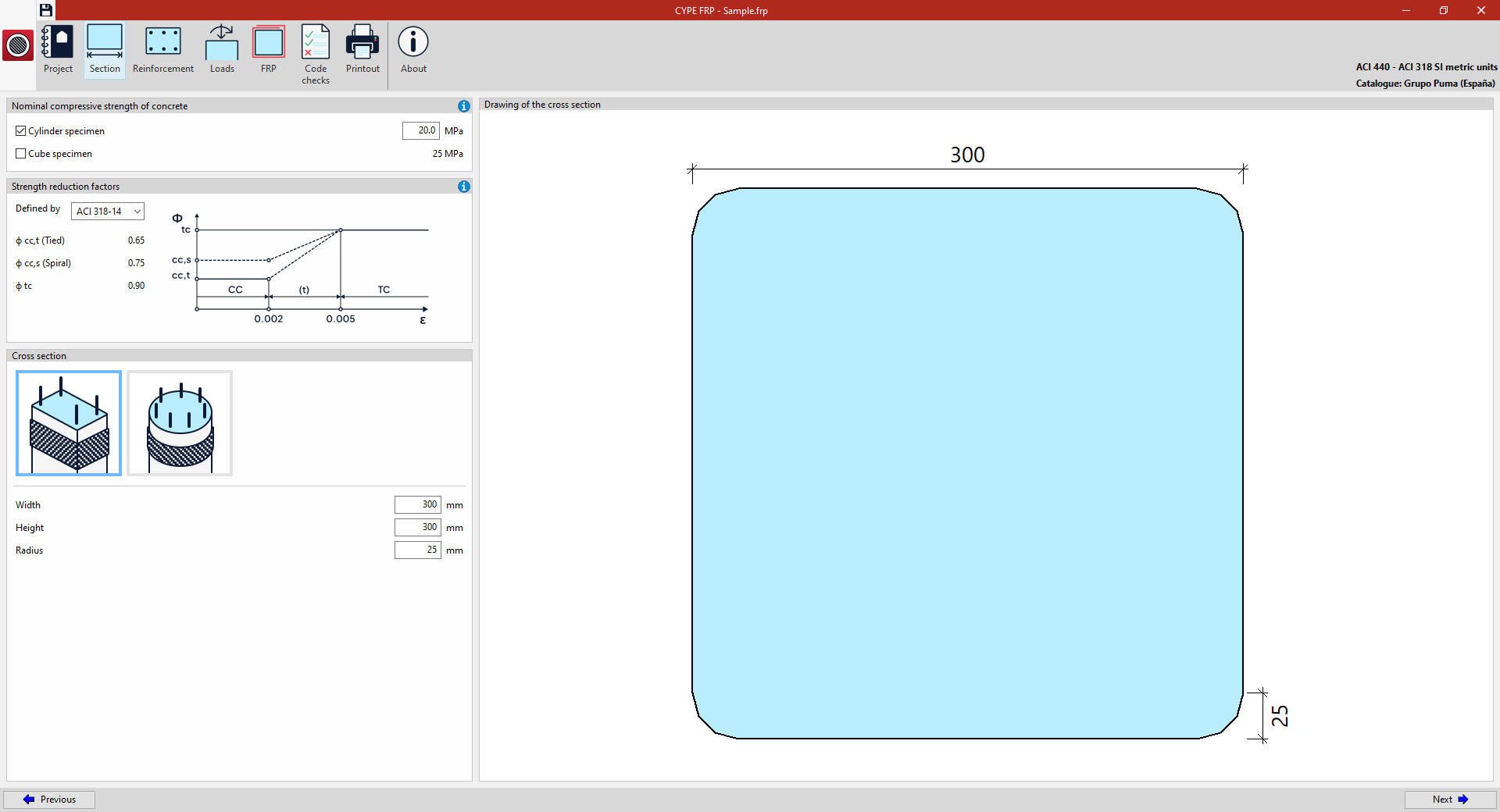
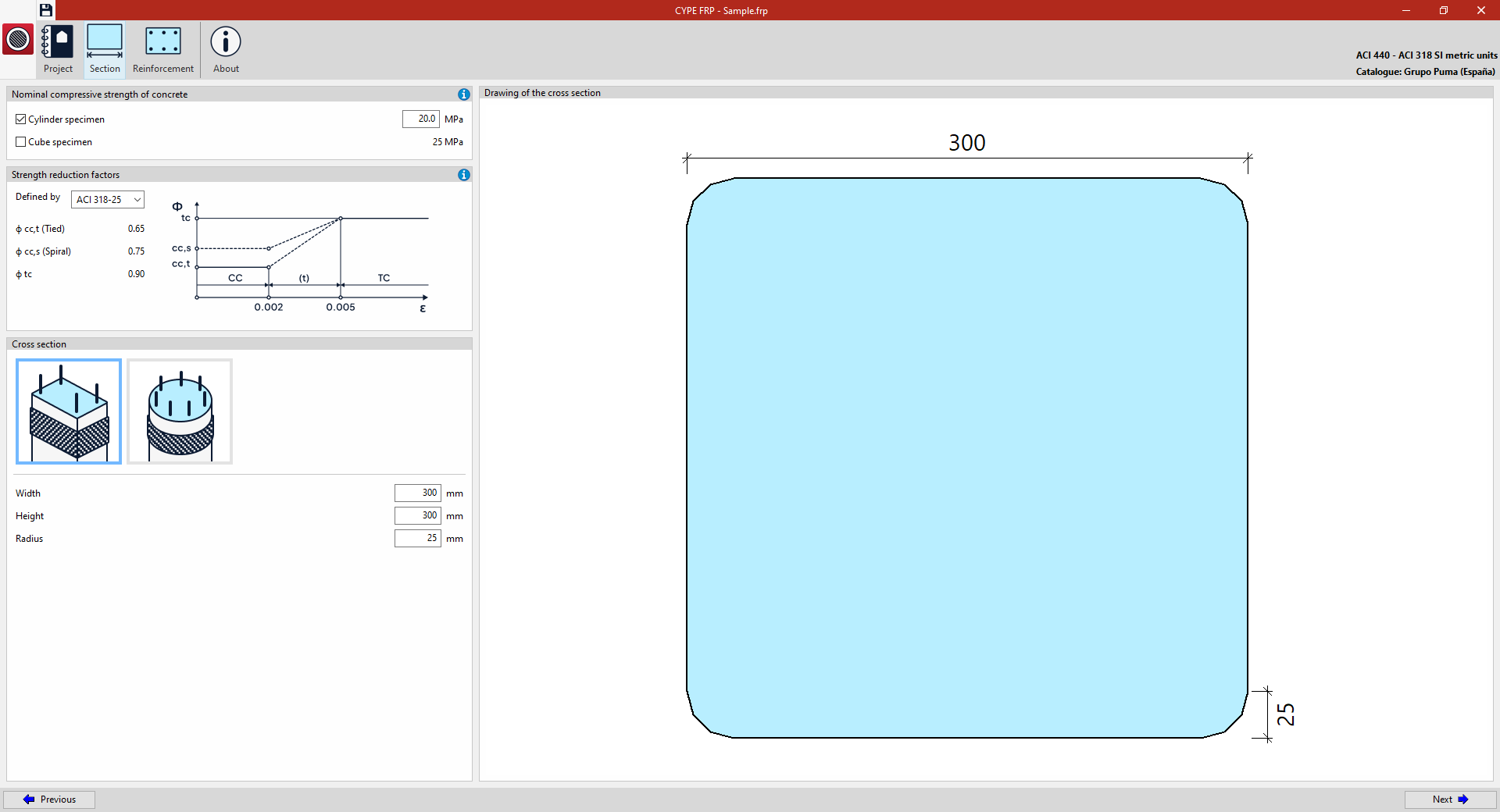
In "Section", accessible from the top of the interface, you can define the material and geometry of the section of the reinforced concrete member to be analysed.
Example: defining the cross-section of a column (analysis in accordance with ACI 440 – ACI 318)
The following details are defined in the "Section" tab:
- Nominal compressive strength of concrete
Calculations shall be carried out in accordance with the compressive strength determined using a "Cylinder specimen". However, you may specify the strength based on a "Cube specimen" by ticking the relevant box.
- Strength reduction factors
These can be "Defined by" "ACI 318-25", in which case the program applies them automatically, or entered directly by the "User". In this case, the following factors are specified:- ϕ cc,t (Tied)
- ϕ cc,s (Spiral)
- ϕ tc
- Cross-section
Specify whether it is a "Rectangular section" (stating the "Width", "Height" and "Radius") or a "Circular section" (stating the "Diameter").
On the right, the defined "Drawing of the cross section" is displayed.
Defining the reinforcement
In the "Reinforcement" section, accessible from the top of the interface, you define the material and layout of the reinforcement in the reinforced concrete section to be analysed.
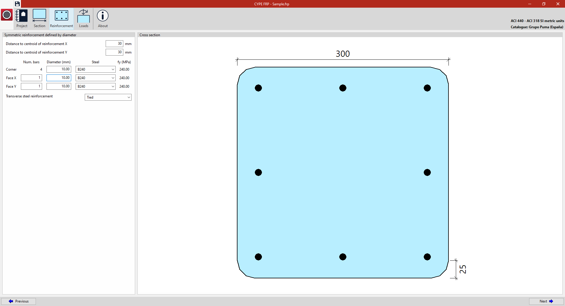
Example: defining the reinforcement layout for a column section (calculation in accordance with ACI 440 – ACI 318)
In the "Reinforcement" section, the following details are defined under "Symmetrical reinforcement defined by diameters":
For rectangular columns:
- The "Distance to centroid of reinforcement X" and the "Distance to centroid of reinforcement Y" are defined, i.e. the distance from the outermost concrete fibre to the centroid of the reinforcing steel.
- Next, for the corners – the "Face X" and "Face Y" of the column – enter the number of bars ("Num. bars") and their "Diameter", and select the reinforcing "Steel" from those available (its "fy" limit is shown on the right). At the bottom, specify whether the "Transverse steel reinforcement" is "Spiral" or "Tied".
For circular columns:
- The "Distance to centroid of reinforcement" is defined as the distance from the outermost concrete fibre to the centre of gravity of the reinforcing steel.
- Next, enter the number of bars ("Num. bars") and their "Diameter", and select the "Steel" grade from those available (its "fy" limit is shown on the right). At the bottom, specify whether the "Transverse steel reinforcement" is "Spiral" or "Tied".
On the right, the "Cross-section" is shown with the defined reinforcement.
Entering loads
In the "Loads" section, accessible from the top of the interface, the loads and load combinations to be used in the analysis are defined.
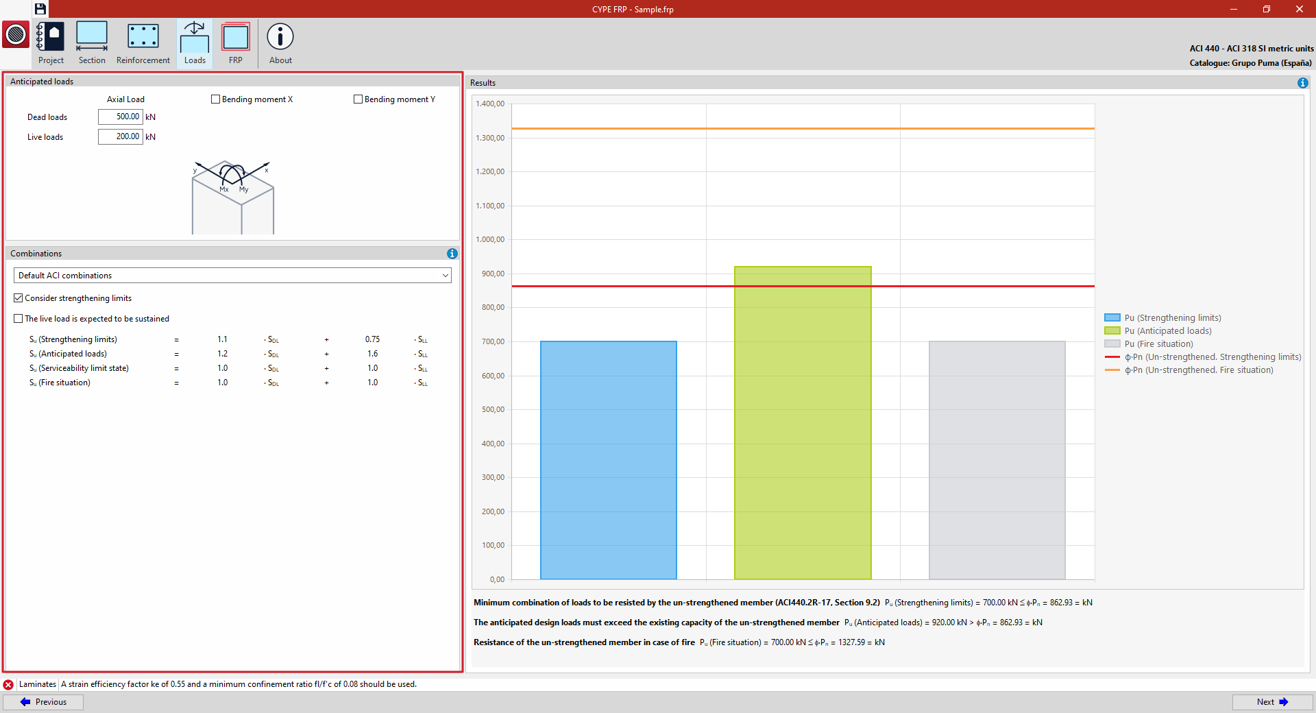
Example: applying loads to a column (analysis in accordance with ACI 440 – ACI 318)
The following details are defined in the "Loads" section:
- Under "Anticipated loads", for the "Dead loads" and/or "Live loads" load cases (in both cases, without any increase and as expected following the reinforcement), enter the value for the "Axial load" and, optionally, for the "X-moment" and the "Y-moment". The program displays a diagram showing the sign convention for these moments with respect to the section axes.
- Under "Combinations", you can choose whether to use the "Default ACI combinations" or the "User-defined combinations". At the bottom, the factors applied (which can be modified if "User combinations" are selected) to the two SLL and SDL load cases (live loads and dead loads) are displayed for the following combinations:
- Su (Strengthening limits)
This combination of loads corresponds to the minimum value that the unreinforced member must be able to withstand. - Su (Anticipated loads)
This combination of loads corresponds to the design load that the reinforced member must withstand. - Su (Serviceability limit state)
This combination of loads corresponds to the value to be used to assess the behaviour of the reinforced member in service. - Su (Fire situation)
This combination of loads corresponds to the value to be taken into account in the event of a fire.
- Su (Strengthening limits)
- In addition, the following options are available under "Combinations":
- Consider strengthening limits
The FRP reinforcement limitation is imposed to safeguard the structure against collapse in the event that the FRP is damaged as a result of an impact, vandalism or other causes, by limiting the maximum reinforcement ratio. This verification confirms that the remaining reinforced concrete section is capable of withstanding a certain level of loads on its own. By disabling this option, the users agree to provide the necessary protection for the FRP to prevent the possibility of this type of damage. - The live load is expected to be sustained
This option should be selected if the live load acting on the structural element is highly likely to be present for prolonged periods (such as in storage areas or bookshops), and it adjusts the factor to equal one.
- Consider strengthening limits
Checking analysis results
In the "Results" panel, to the right of the "Loads" section, which can be accessed from the top of the interface, you can view the results of the analysis carried out on the defined cross-section.
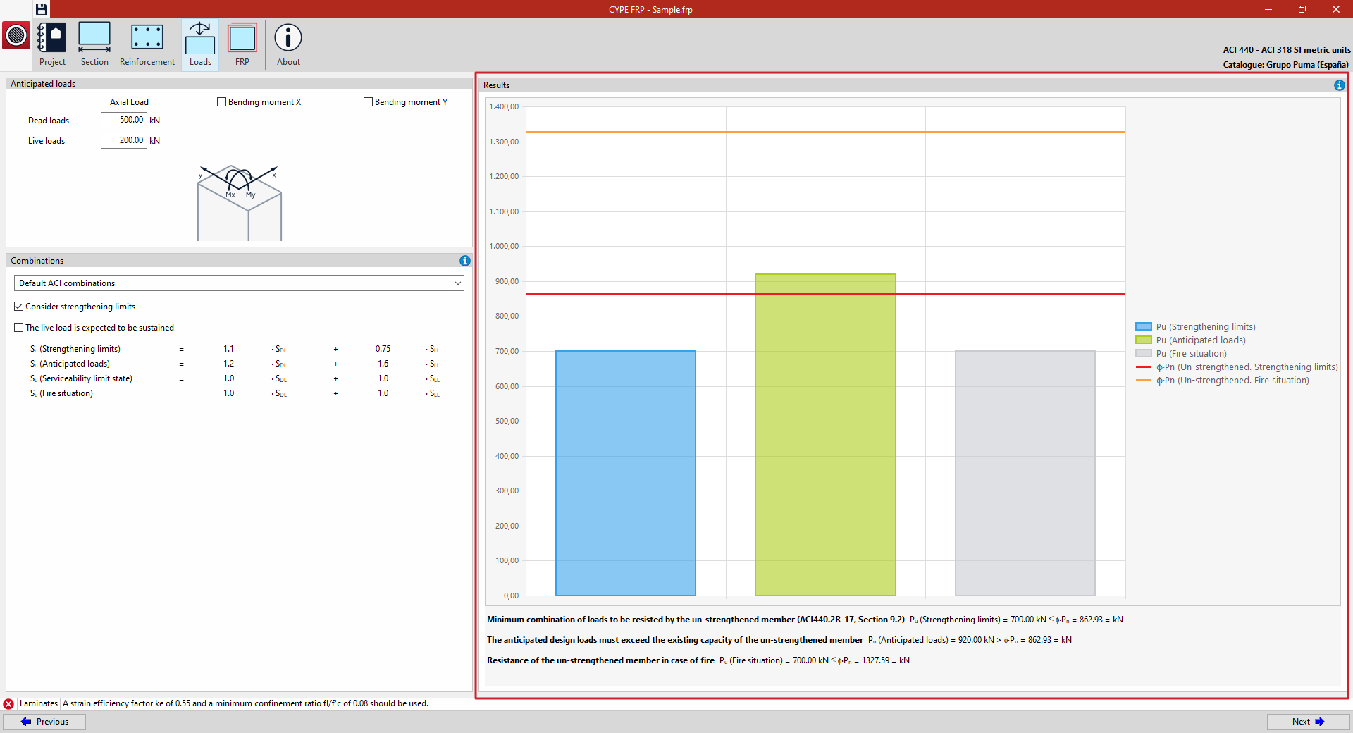
Example: analysis of results for a column subjected to axial load without moments (analysis in accordance with ACI 440 – ACI 318)
In the "Results" panel, the program displays a graph containing the following information, which is updated based on the data entered previously:
- The columns show the values calculated for the load applied to the element in the different combinations ("Pu (Strengthening limits)", "Pu (Anticipated loads)" and "Pu (Fire situation)").
- The lines show the resistance of the unreinforced element when the reduction factor is applied in the different cases ("ϕ·Pn (Unreinforced. Strengthening limits)" and "ϕ·Pn (Unreinforced. Fire situation)").
The program carries out the following checks, which are displayed at the bottom:
- Minimum combination of loads to be resisted by the un-strengthened member (ACI 4402.R-17, Section 9.2)
Pu (Reinforcement limits) ≤ ϕ·Pn (Unreinforced. Reinforcement limits)
The unreinforced member must be capable of withstanding a certain combination of expected loads, without the contribution of the FRP. If this condition is not met, the member will not be able to achieve the required reinforcement ratio.
- The anticipated design loads must exceed the existing capacity of the un-strengthened member Pu (Design loads) > ϕ·Pn (Unreinforced. Reinforcement limits)
The user must enter a combination of design loads that exceed the load-bearing capacity of the existing unreinforced member.
- Resistance of the un-strengthened member in case of fire
Pu (Fire scenario) ≤ ϕ·Pn (Unreinforced. Fire scenario)
In the event of loss of the FRP due to high temperatures, the residual resistance of the unreinforced member must be greater than the fire load combination. Otherwise, the FRP must be protected against fire. This check does not assess the change in the existing member’s strength over the course of the fire; this must be determined in accordance with current standards.
When the anticipated loads exceed the strength of the unreinforced member, the program will enable the "FRP" section, where the FRP reinforcement is defined and/or analysed.
Defining FRP reinforcement
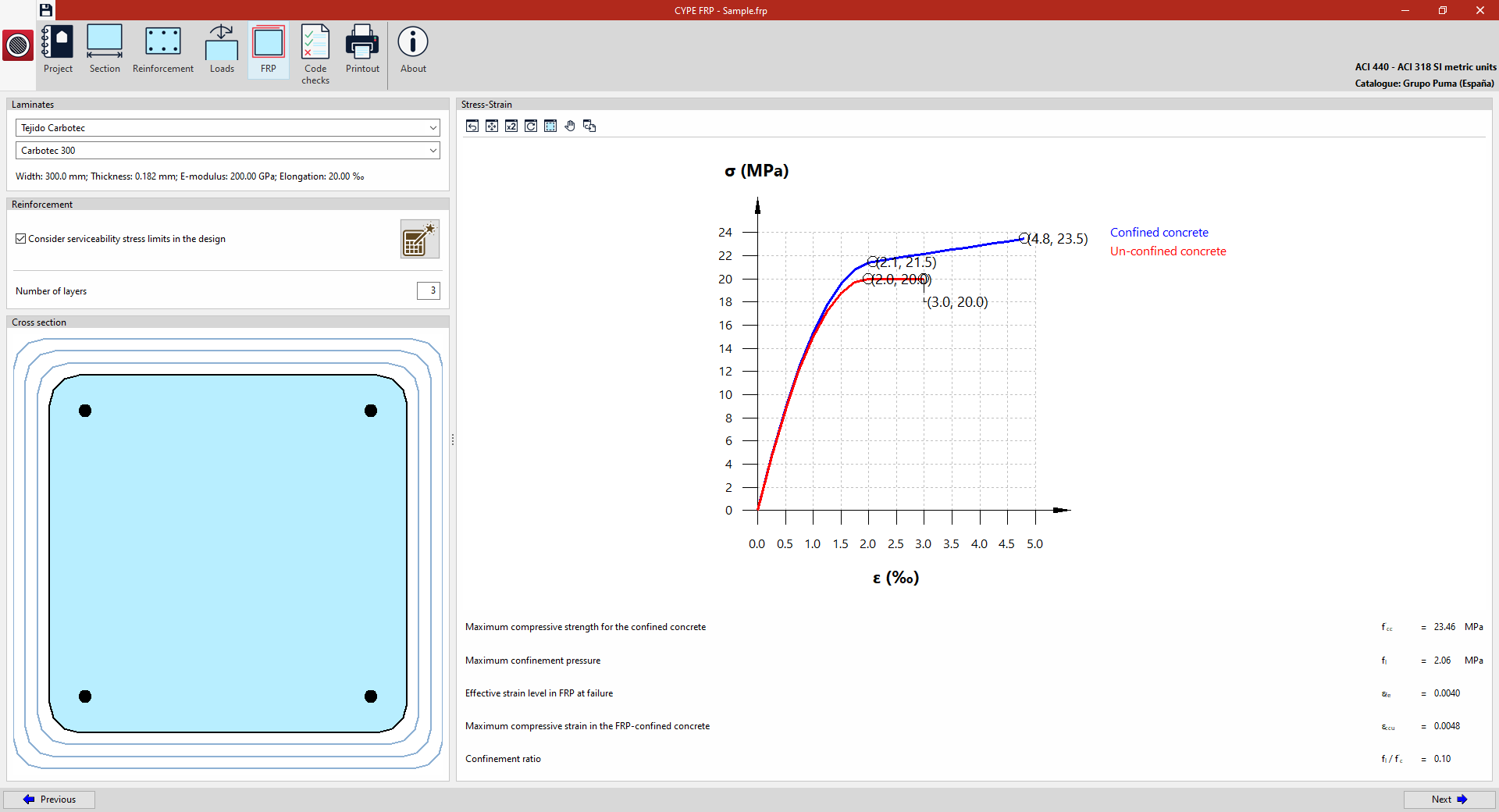
In the "FRP" section, accessible from the top of the interface, the FRP reinforcements in the analysed member are defined.
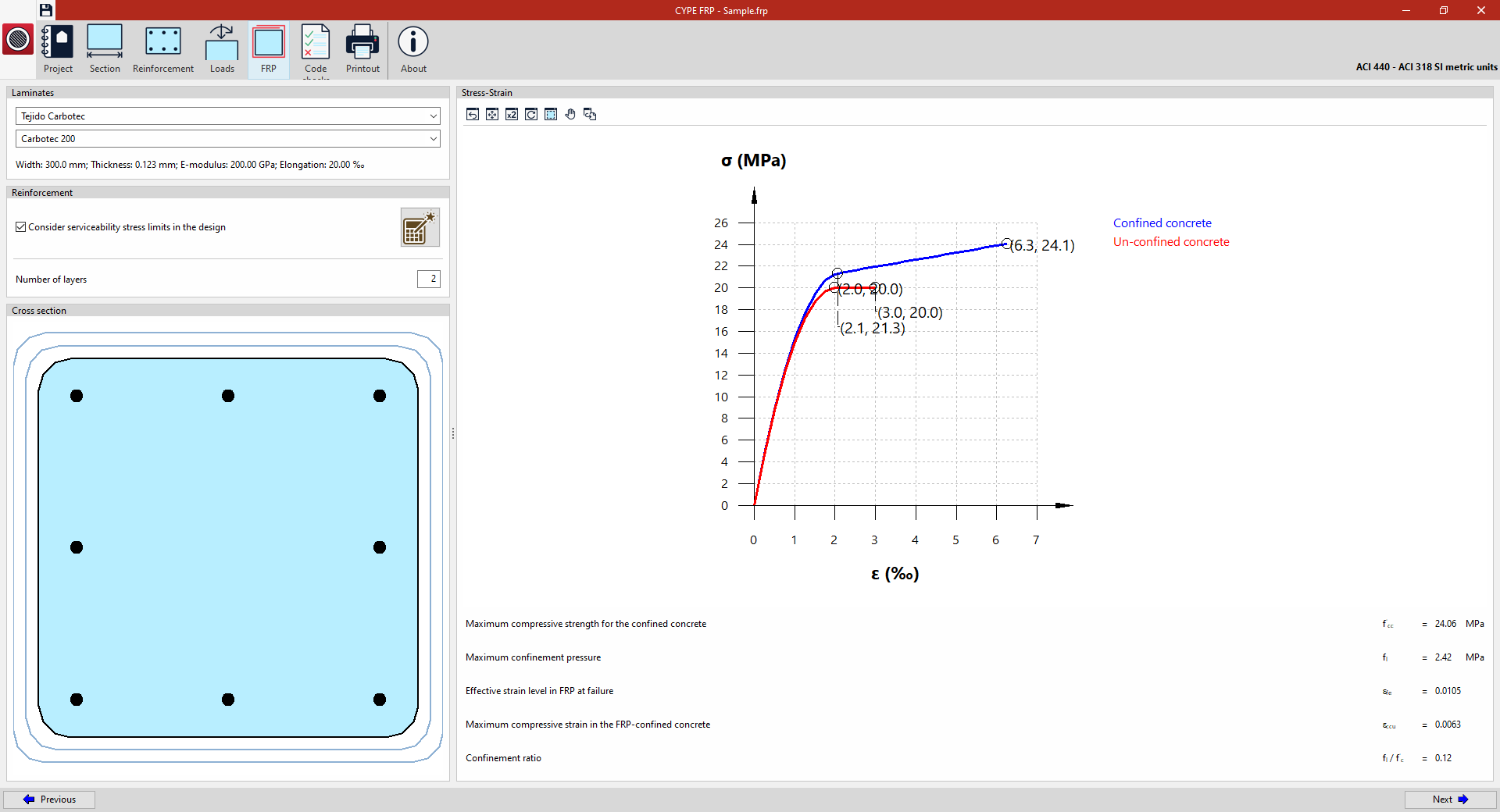
Example: FRP reinforcement of a column (analysis in accordance with ACI 440 – ACI 318)
The following details are defined in the "FRP" section:
- In the "Laminates" section, the specific series and product from the selected manufacturer are chosen when creating the project. The program displays the properties of the selected product, such as "Width", "Thickness", "E-Modulus" and "Elongation".
- In the "Reinforcement" section, you can either enter the "Number of layers" of FRP reinforcement manually or click the button provided to automatically carry out the "Calculation of the necessary number of FRP laminates". You can also "Consider serviceability stress limits in the design" by ticking the relevant box.
- The bottom right-hand corner shows the "Cross-section" of the element, including a view of the FRP reinforcement layers.
- On the right, a "Stress-Strain" diagram of the cross-section is shown, with two graphs corresponding to "Unconfined concrete" and "Confined concrete", indicating the number of layers of the selected product entered.
At the bottom, relevant parameters are shown, such as the "Maximum compressive strength for the confined concrete", the "Maximum confinement pressure", the "Effective strain level in FRP at failure", the "Maximum compressive strain in FRP-confined concrete", and the "Confinement ratio".
Once the dimensions of the FRP reinforcement have been analysed, the program enables the options that let you view the "Check" of the cross-section on screen and to "Print" the reports.
Checking the analysis results
In the "Results" panel, to the right of the "Loads" section, which can be accessed from the top of the interface, you can view the results of the analysis carried out on the defined cross-section.
Example: checking the cross-section of a column (analysis in accordance with ACI 440 – ACI 318)
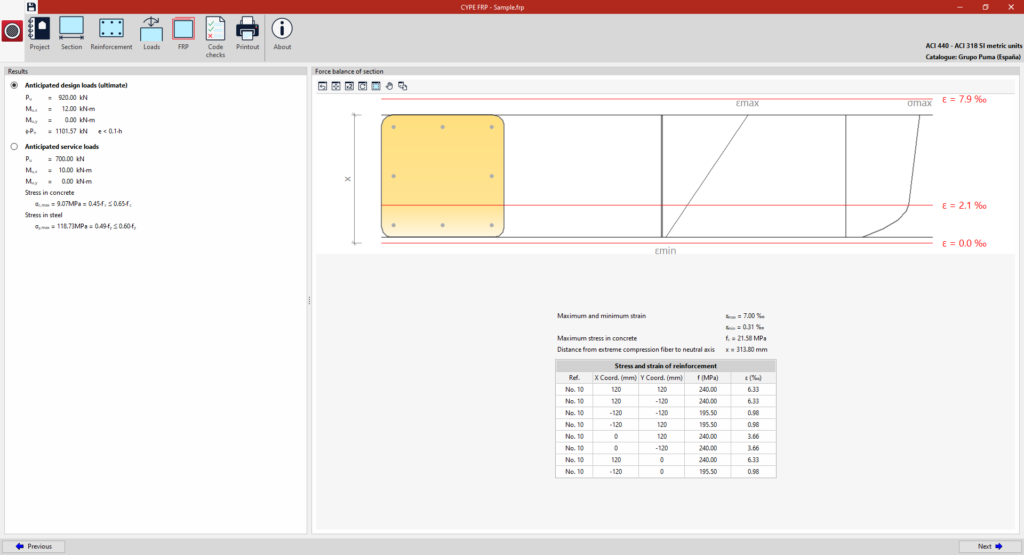
The "Verification" section displays:
- On the left, the "Results" obtained from the analysis, for both the "Anticipated design loads (ultimate)" and the "Anticipated service loads", including axial forces and moments, concrete stress and steel stress.
- On the right, the "Force balance of section" diagram for the selected loads, showing the cross-section layout and reinforcement, along with the strain and stress graphs. Shown are the "Maximum and minimum strain", the "Maximum stress in concrete", and a table showing the "Stress and strain of reinforcement", including the reference number of each bar and its X and Y position coordinates within the cross-section.
Printing reports
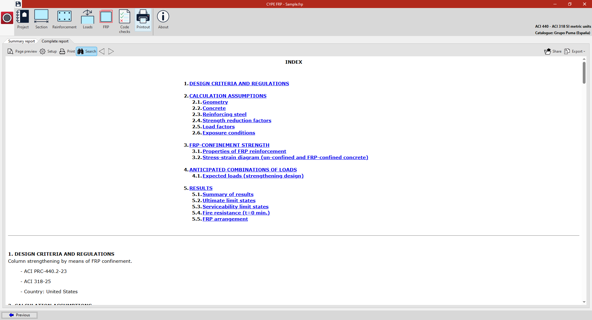
In the "Print" section, which can be accessed from the top of the interface, you can view detailed reports containing the analysis and results for the FRP reinforcement of the structural member.
Example: results obtained following the analysis of FRP reinforcement for a column (analysis in accordance with ACI 440 – ACI 318)
The "Print" section lets you obtain the following documents:
- A "Summary report", which includes the design criteria and regulations used, and a summary of the results.
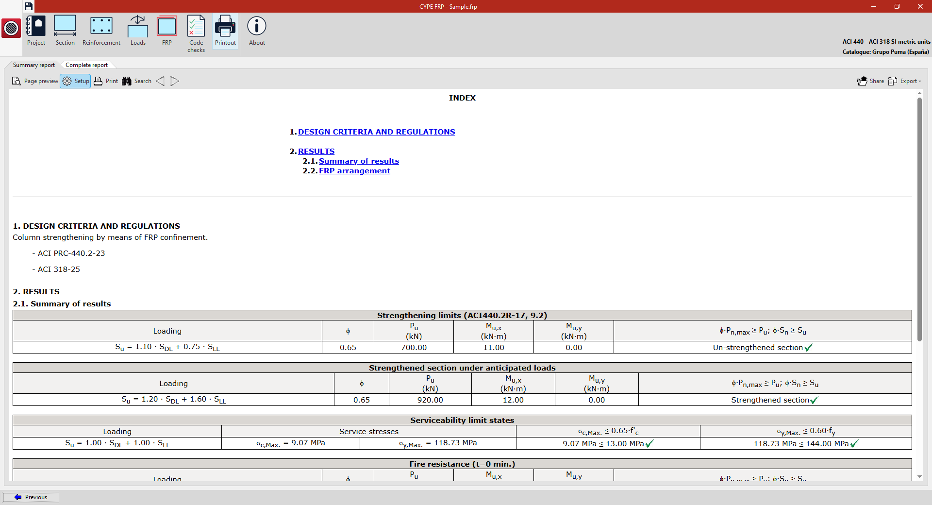
- A "Complete report" of the verification, including the design criteria and regulations used, the calculation assumptions adopted, the FRP confinement strength provided, the load combinations considered, and the results obtained from the analysis.
These documents can be viewed on screen, printed directly or exported in different formats (such as RTF, DOCX or PDF) using the relevant options.