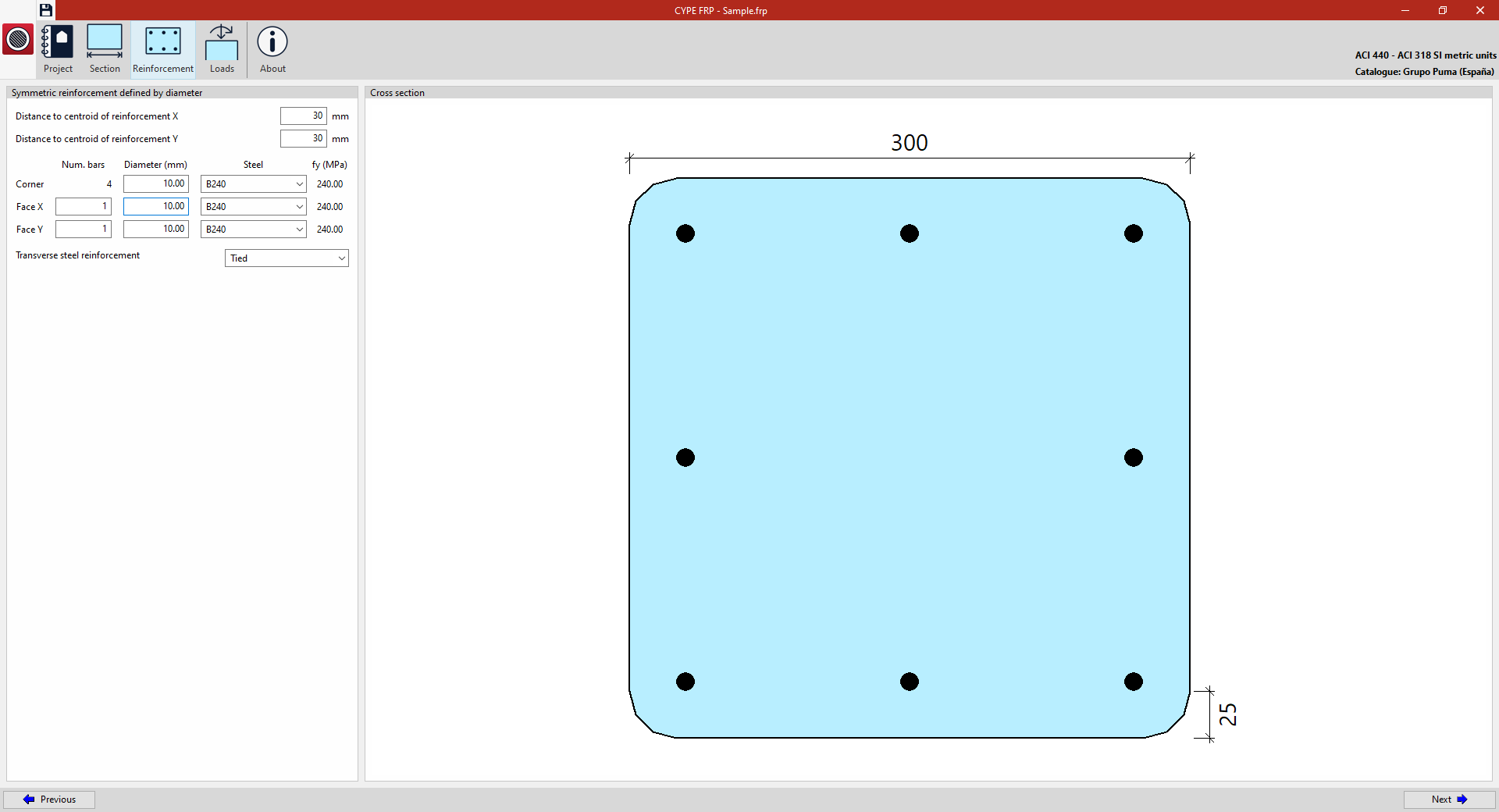

Defining the reinforcement
In the "Reinforcement" section, accessible from the top of the interface, you define the material and layout of the reinforcement in the reinforced concrete section to be analysed.
Example: defining the reinforcement layout for a column section (calculation in accordance with ACI 440 – ACI 318)
In the "Reinforcement" section, the following details are defined under "Symmetrical reinforcement defined by diameters":
For rectangular columns:
- The "Distance to centroid of reinforcement X" and the "Distance to centroid of reinforcement Y" are defined, i.e. the distance from the outermost concrete fibre to the centroid of the reinforcing steel.
- Next, for the corners – the "Face X" and "Face Y" of the column – enter the number of bars ("Num. bars") and their "Diameter", and select the reinforcing "Steel" from those available (its "fy" limit is shown on the right). At the bottom, specify whether the "Transverse steel reinforcement" is "Spiral" or "Tied".
For circular columns:
- The "Distance to centroid of reinforcement" is defined as the distance from the outermost concrete fibre to the centre of gravity of the reinforcing steel.
- Next, enter the number of bars ("Num. bars") and their "Diameter", and select the "Steel" grade from those available (its "fy" limit is shown on the right). At the bottom, specify whether the "Transverse steel reinforcement" is "Spiral" or "Tied".
On the right, the "Cross-section" is shown with the defined reinforcement.