Configuring general project data
In the "General data" menu at the top, you will find the "Edit general project data" option, which allows you to enter general information about the installation, such as materials and ground conditions, the parameters, limits and coefficients used in the analysis, and excavation data.

The options available are as follows:
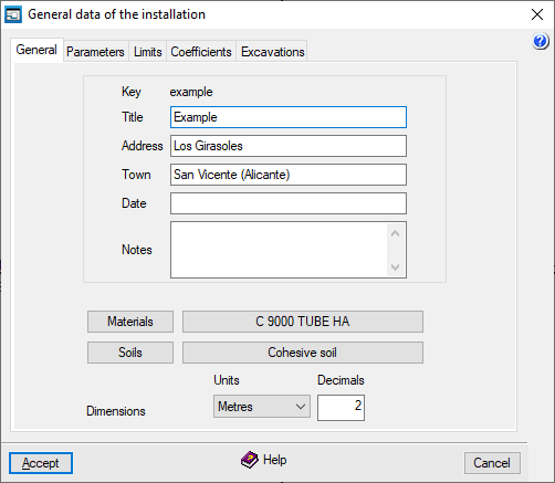
"General" tab
This allows you to enter the following general details, which will appear in the design reports, within the installation description:
- Key
Name of the job. To change it, select "File", then "Save as". - Title
- Address
- Town
- Date
- Notes
In addition, the following options are available:
- Materials
Allows you to manage the materials. - Soils
Allows you to manage the soils. - Settings
for the "Units" and the number of "Decimals" used.
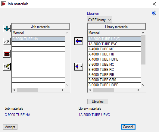
Materials management
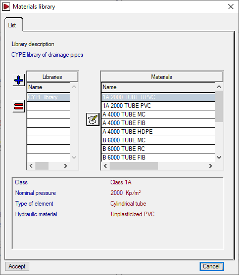
By clicking on the "Materials" button, you can manage the materials used in the site’s pipework, as well as the available material libraries. The window that appears displays two lists:
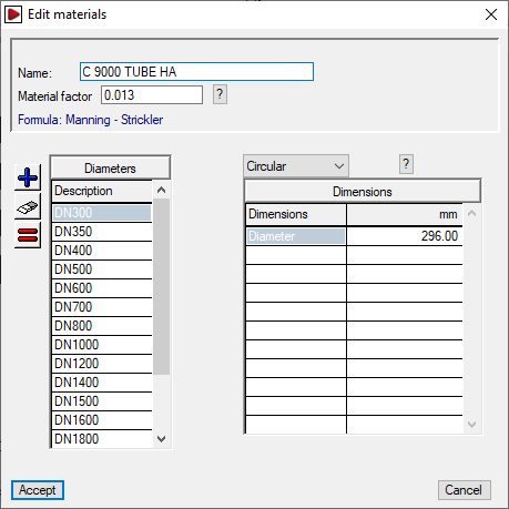
- The list on the left shows the "Job materials". You can create a material manually using the tools on the left or import it from the library materials. When adding or editing a project material, the "Name" and "Material Factor" are specified based on the selected formulation.
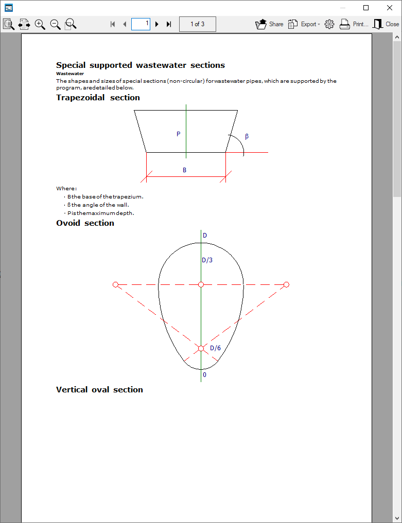
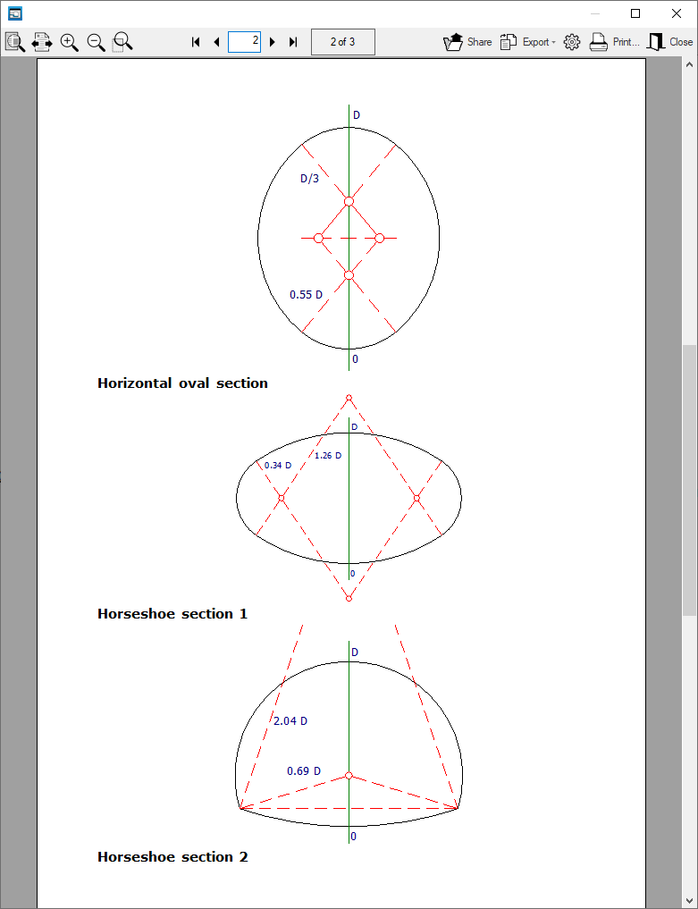
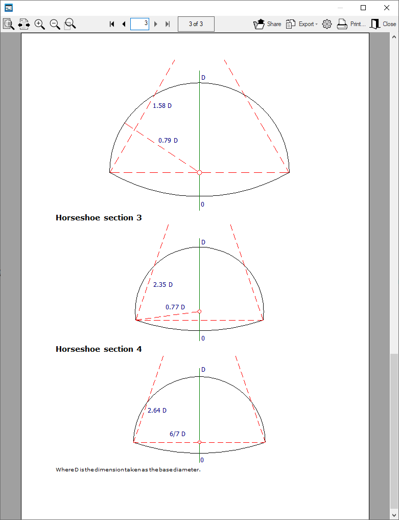
Further down, the “Diameters” table lists the section references associated with the material. On the right, for each section in the list, the section type is selected from the drop-down menu, and the values for its “Dimensions” are detailed, which will depend on the selected section type. The available section types include the following:- Circular, Trapezoidal, Ovoid, Vertical oval, Horizontal oval, Horseshoe
- The list on the right shows the "Library materials". At the top, you can select the library you wish to view. The program includes a default library. You can view the internal data for each library by clicking on the "Libraries" button at the bottom; there, you can define the "Library description" and its "Abbreviation", and for each material included, the "Name" and "Material factor" are displayed based on the selected formulation, as well as the associated section lists.
The first button between the two lists allows you to create a site material by importing information from one of the materials available in the library. The second button allows you to add the grades of the selected library material (on the right) to the selected job material (on the left).
Soils management
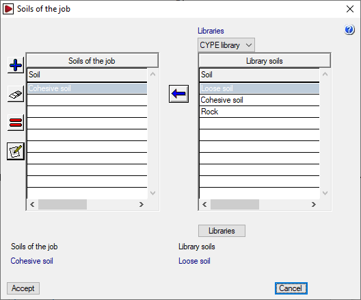
By clicking on the "Soils" button, you can manage the terrains for the project, as well as the available terrain libraries. The window that appears displays two lists:
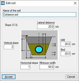
- The list on the left shows the "Site Terrains". You can create a terrain manually using the tools on the left, or import one from the library terrains. When adding or editing a soil in the job, the “Soil name” and the following geometric parameters are specified: “Lateral distance”, “Infill”, “Bed”, “Minimum width”, “Vertical slope” and “Horizontal slope” (which form the “Slope” ratio shown next to the graph).
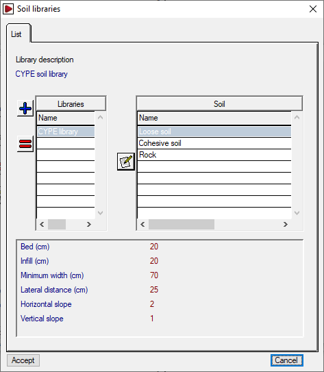
- The list on the right shows the "Library soils". At the top, you can select the library you wish to display. The program includes a default library. You can view the internal data for each library by clicking on the "Libraries" button at the bottom; there, you can define the "Library description", and its "Abbreviation", and for each plot included, the "Plot name" and the aforementioned geometric parameters are displayed.
The first button between the two lists allows you to create a soil in the job by importing information from one of the soils available in the library. The second button allows you to add the sections of the soils selected from the library on the right to the job soil selected on the left.
To continue creating a new job, you must create at least one material and one soil.
The materials and sites will be available when editing each section via "Spans", "Edit design data".
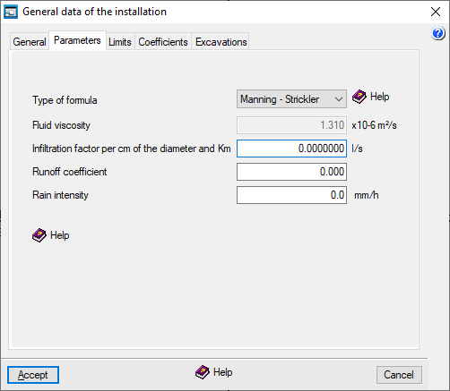
"Parameters" tab
This allows you to define the following design parameters:
- Type of formula
Allows you to select the formulation used to calculate the sections of the sewerage network from the following:- Manning – Strickler
- Prandtl – Colebrook
- Tadini
- Bazin
- Sonier
- Kutter
- Ganguillet - Kutter
- Fluid viscosity
Kinematic viscosity of the fluid; by default, the value 1.31 × 10⁻⁶ m²/s is displayed (1 m²/s = 10,000 Stokes). - Infiltration factor per centimetre of the diameter and kilometre (in l/s)
This factor defines linear inflows into pipelines due to porosity, whether natural, caused by poor maintenance, or intentional. It is defined at a general level and applies to all sections of the project. If you wish to apply it specifically to a particular section, use the corresponding option in the "Sanitation" tab of the "Section edit" window (under "Sections", "Edit design data").
A value can be estimated between 0.0058 l/s = 0.5 m³/day (for new pipes) and 0.0463 l/s = 4 m³/day (for poorly maintained pipes). - Runoff coefficient: A
value of 0.95 may be used for pedestrian areas, roads and plots, and a value of 0.50 for green spaces. - Rain intensity
The maximum rainfall intensity expected for a given return period, corresponding to a rainfall event of a duration equal to the concentration time.
| Note: |
|---|
| The values for "Runoff coefficient" (C, between 0 and 1) and "Rain intensity" (I, in mm/h) entered here will appear in the "Node editing" window for new nodes (as data in the "Contribution" column, if “Rain” loads are selected) and, together with the catchment area (S, in m²), allow the rainwater flow rate (Q, in m³/h) to be calculated using the expression Q=C*I*S/1000. |
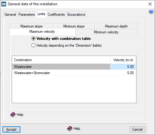
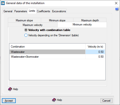
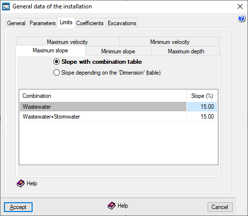
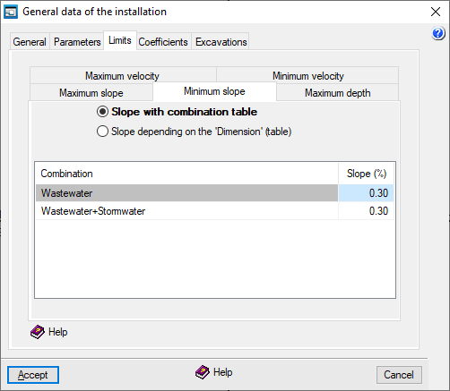
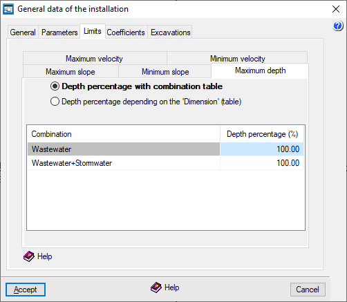
"Limits" tab
This tab allows you to set speed, gradient and draught limits for sections of the installation. These limits operate in two ways:
- If you select the "Analyse" option from the "Analysis" menu, a warning is displayed for those elements of the installation that fall below the minimum values or exceed the maximum values.
- If the "Design" option in the "Analysis" menu is used, the program restricts the system's operation to values within the defined minimum and maximum limits, where possible, as design limits.
The various tabs are used to define the "Maximum speed", "Minimum speed", "Maximum gradient", "Minimum gradient" and "Maximum draught" for the sections.
This can be done:
- By combination table
For each entry, the speed limit, gradient limit or gradient percentage is defined for each combination specified under "General data", "Edit combinations". - Based on "Dimension" (table)
For each entry, the speed limit, gradient limit or draught percentage is defined, which applies to pipelines with dimensions equal to or smaller than those specified. For dimensions larger than those specified, the limit for the largest dimension in the table applies.
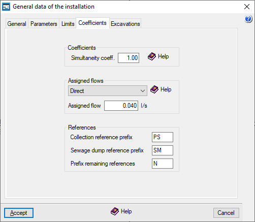
"Coefficients" tab
Coefficients
This allows you to set the following coefficient, which is applied across the board to all analyses for the project:
- Simultaneity coefficient
This allows you to increase or decrease the inflows into the collection wells. It is defined as a ratio of one and is applied to the wells in all combinations. This makes it possible to simulate operations at different times of the day or seasonal changes. By default, a value of one is set.
Assigned flows
This allows you to specify whether the loads for collection wells are defined by default directly or by allocation.
- Direct
The discharge will be fed directly into the flow units. - Per allocation
The discharge will be calculated based on the flow rate per allocation (which corresponds to the value entered in the "Allocation" field) and the corresponding number of units.
The load values and their definition type can be edited later in the edit panel for each node.
References
This allows you to set the prefixes that are automatically added to the references of the installation nodes when they are added to the workspace, whether they are collection wells, discharge points or other nodes:
- Collection reference prefix
- Sewage dump reference prefix
- Remaining reference prefix
References can be edited later in the edit panel for each node.
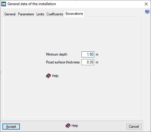
"Excavations" tab
This tab allows you to define the following parameters relating to the site's excavations:
- Minimum depth
Allows you to set an alarm that alerts you when any point in the installation falls below this value (in the "Analysis results" report that appears after using the options in the "Analysis" menu). The minimum depth is measured from the ground level to the top edge of the inner face of the duct. - Road surface thickness
This indicates the default distance between the road surface and the modified ground level. By default, this value is subtracted from the road surface elevation (entered in the "Edit node" panel) to obtain the ground level without the need to enter it manually. Furthermore, if the ground level is changed in that panel, a warning will be displayed if the specified road surface thickness is not met.
| Note: |
|---|
| Where there are multiple road surface thicknesses in the project, if the "Road surface thickness" value is changed in this section, any new nodes added from this point onwards will be analysed using the new thickness, but the previous thickness will be retained for nodes added earlier. |