Entering and editing spans
The "Spans" menu at the top of the program interface contains the following options for entering and editing installation spans:
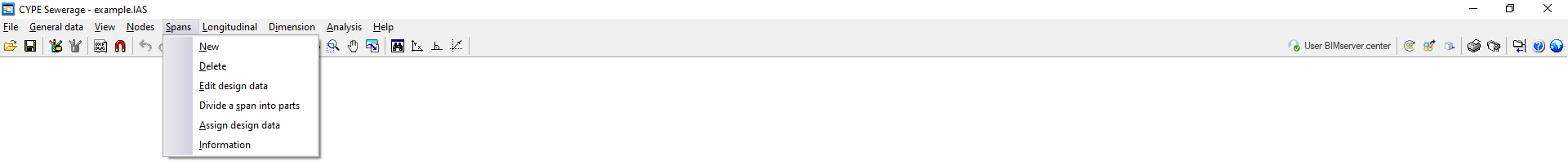
New
This allows you to insert a new span into the workspace. This can be done:
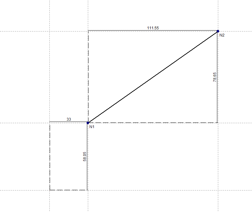
- By selecting two previously created nodes from "Nodes", "New".
- Or by simply selecting two points on the workspace, which will define the end nodes of the span. This means there is no need to enter the nodes defining the span beforehand. When doing this, you must specify the absolute or relative coordinates of each node or capture points from a template, just as you would when adding new nodes.
In addition, the following is taken into account:
- If, when creating a new span, it crosses an existing span, a new node will be created at that intersection.
- If, when you insert a span, the mouse pointer is positioned over the centre of a node, the end of the span will be that node. Otherwise, a new node will be created at that point.
- You can also click on a previously entered span to start from that point and create a node at the desired location.
The end nodes of the inserted spans are created by default as transition nodes; that is, nodes without load input that allow changes in direction whilst maintaining the span’s continuity in the analysis. They can subsequently be edited via “Nodes”, “Edit design data”.
| Note: |
|---|
| The installation must be interconnected; in other words, all nodes entered in the project must be connected by spans belonging to the same network with a single discharge point. It is not possible to include two separate networks in the same file. |
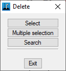
Delete
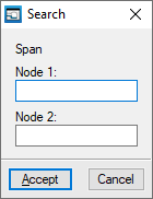
This allows you to delete the selected span. You can use the left mouse button to draw a rectangular selection area on the screen to delete multiple spans. Furthermore, clicking the right mouse button brings up options to "Select" a single span, perform a "Multiple selection" span by span, or "Search" for a span using the coordinates of its endpoints.
When a span is deleted, the end nodes are also removed if they belong solely to the deleted span.
Edit design data
This allows you to edit the selected span. You can use the left mouse button to draw a rectangular selection area on the screen to edit multiple spans, selecting the fields you wish to edit. Furthermore, clicking the right mouse button brings up options to "Select" a single span, perform a "Multiple selection" span by span, or "Search" for a span using the coordinates of its end nodes.
In the edit window that appears, enter the details of the span:
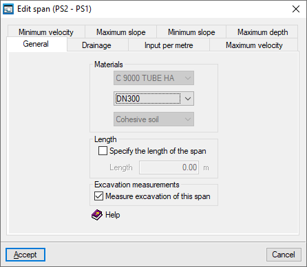
- "General" tab
- Materials
- Span material
Determines the range of diameters available for the span, both for manual selection and for preliminary design. In the latter case, the program will attempt to find a diameter that meets the requirements without changing the span material. - Pipe diameter
This determines the main design parameters for the pipe span. During preliminary sizing, the diameter that best fits the existing network is selected from among those defined for the material chosen for the pipe span. - Span terrain
The terrain where the trench through which the span runs is excavated. This parameter does not appear if no terrain has been selected for the project.
- Span material
- Length
The program allows you to determine the length of the span based on the drawing provided or to enter the value directly. In the first case, the "Specify span length" checkbox remains unchecked, and the length of the span is calculated based on the coordinates of the end nodes (including their elevation). In the second case, the "Specify the length of the span" checkbox is enabled, and the length value used to analyse that span is entered. This option allows you to enter diagrams that do not need to be drawn to scale.- Specify the length of the span (optional)
- excavation survey
- Measure excavation of this span (optional)
- Materials
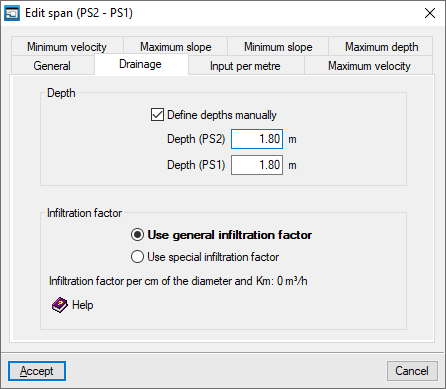
- "Drainage" tab
- Depth
- Set depths manually (optional)
When this box is ticked, the program allows you to set the depth of the duct at the end nodes of the span, measured from the ground level at the nodes to the lower edge of the inner surface of the duct.
- Set depths manually (optional)
- Infiltration factor
- Use general infiltration factor
If this option is selected, the program will use the infiltration factor defined for the entire project under "General data", "Edit general project data". - Use specific infiltration factor
If this option is selected, you must define the infiltration factor per centimetre of diameter and per kilometre for the span being edited.
- Use general infiltration factor
- Depth
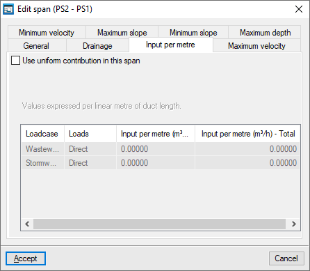
- "Inflow per metre" tab
This allows you to define a uniform inflow rate for the span. The values are expressed per linear metre of pipeline length.- Use uniform contribution this span (optional)
When this box is ticked, the program displays a table at the bottom that allows you to define the inflow rate for each loadcase. This table contains the following columns:- Loadcase
- Loads
The load can be defined in two ways:- Direct
- By allocation
- Rainwater
- Inflow per metre
The inflow rate per linear metre is defined by entering its value directly if the "Direct" option has been selected; by entering a value for “Allocation” and the “Number of units” to be considered, if the “By allocation” option has been selected; or by defining the “Runoff coefficient”, the “Slope area” and the “Rainfall intensity”, if the “Rainfall” option has been selected. - Total inflow per metre
Displays the total inflow rate per linear metre of pipeline.
- Use uniform contribution this span (optional)
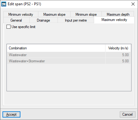
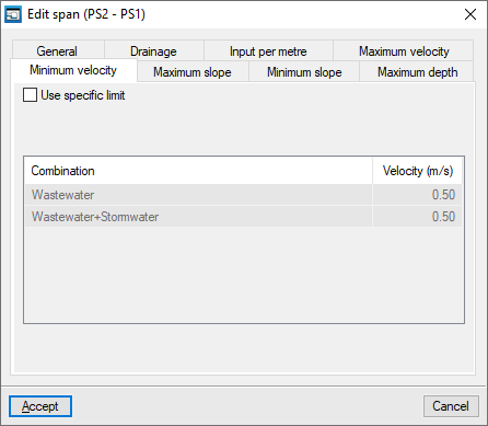
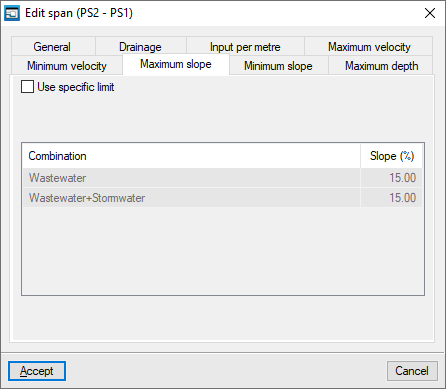
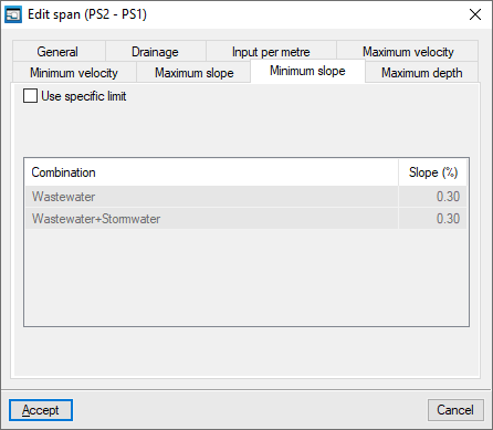
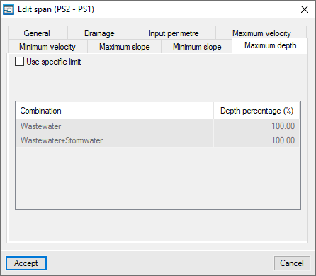
- The "Maximum velocity", "Minimum velocity", "Maximum slope", "Minimum slope" and "Maximum depth" tabs
These tabs allow you to enter specific limits for velocity, slope and depth percentage for the span being edited, for each of the loadcase combinations shown in the table.- Use custom limit (optional)
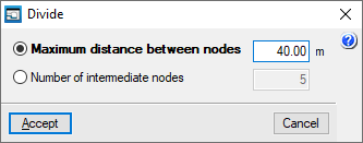
Divide a span into parts
This allows you to select a span and split it into several spans, automatically creating nodes along the span. This can be done by specifying the "Maximum distance between nodes" or the "Number of intermediate nodes".
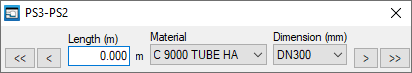
Assign design data
It allows you to quickly assign data to spans.
When you click on the option, a small window opens in the top-left corner of the screen. At the same time, the selected span will be highlighted in yellow; initially, the one with the lowest node references. You can review and/or modify the span’s details (such as length, material and dimensions). You can navigate through all the spans using the relevant buttons.
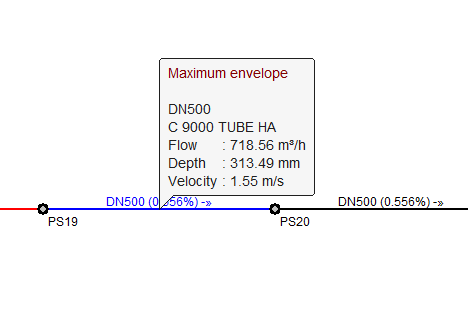
Information
This allows you to view the data entered in the span.
If the job has been analysed, the analysis results for the span under the currently selected loadcase are also displayed. Furthermore, clicking on the span will open a window where you can view the results for any loadcase, combination, envelope and oscillation, both analytically and graphically. The "Graphs" button displays the "Flow", "Depth" and "Velocity" graphs for the different combinations.