Inserting and editing valves, pumps and other components
The "Elements" menu at the top of the program interface contains options for inserting and editing special elements in the pipework, such as various types of valves and booster pumps.

New
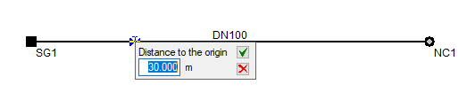
This allows you to define one or more special elements in each section at a specified distance from the node.
To do this, after selecting this option, right-click to open the "Edit element" window, where the element type is specified. If you do not click this button, a control valve will be entered by default; you can then define it via "Elements", "Edit analysis data". Finally, select a point on a previously entered section. At this point, enter the distance to the origin of the element.
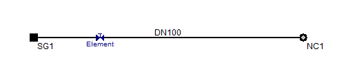
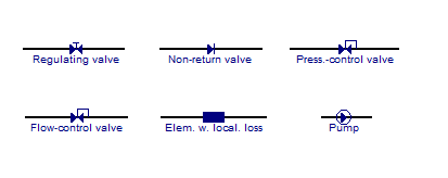
Each element has a different icon to make it easier to locate. Once an element has been added, you can edit, delete or move it using the relevant options.
Delete
This allows you to delete the selected special element.
Move
This allows you to reposition the selected special element. After clicking on it, click on another point to specify the new position.
Copy
This allows you to duplicate the selected special element. Click on the element you wish to duplicate, then click on a section at the new position.
Edit analysis data
This allows you to edit the details of a special element that has already been entered.
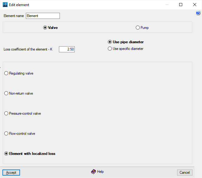
In the "Edit item" window, you can configure the following settings:
- Element name
- Component type: Valve / Pump
Depending on whether valves or pumps are installed, different settings will be required:
Valve editing
- Loss coefficient for an open valve - K / Element loss coefficient - K (for "Element with localised losses")
This allows the dimensionless coefficient for local losses to be defined. This coefficient depends on the type of element in question (bends, elbows, tees or other fittings, open or partially closed valves). Usually, this pressure drop term is measured experimentally and, particularly in the case of valves, depends on the manufacturer’s design. Generally, K decreases as the diameter increases. - Diameter used
By default, the diameter of the pipe in which the component is installed can be used, or a specific diameter can be defined:- Use pipe diameter
- Use specific diameter
- Inner diameter
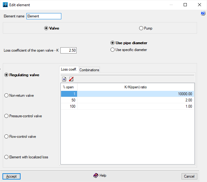
- Regulating valve
A valve that creates pressure drops in the system when set to intermediate positions, with the aim of inserting a pressure drop into the system, thereby altering the pressure distribution within it.- "Loss coefficient" tab:
Table showing the relationship between losses and the valve opening.- Opening percentage, K/K ratio (open)
- "Combinations"
tab: Allows you to set different opening angles for each combination.- Combinations, % open
- "Loss coefficient" tab:
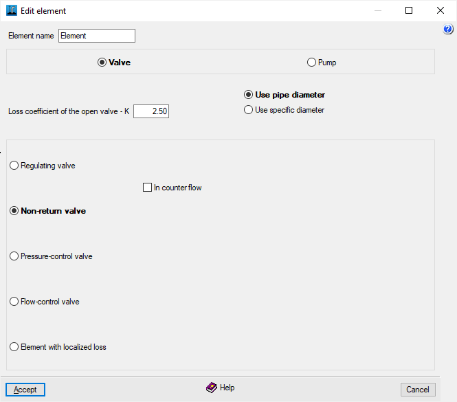
- Non-return valve
A valve that only allows water to flow in one direction.- It is in the opposite direction (optional)
This allows you to specify whether the direction of the valve is the same as that of the pipe in which it is located (from source to end) or whether it is in the opposite direction.
- It is in the opposite direction (optional)
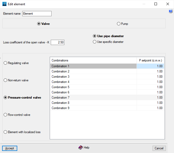
- Pressure-control valve
Pressure-piloted regulating valve. Controlling its closed position ensures that the set pressure is reached downstream of the valve, provided that the upstream pressure is higher than this. Different pressure settings can be defined for each combination. If the system pressure falls below the set value, only the losses associated with the valve being open will be taken into account.- Combinations, Setpoint pressure
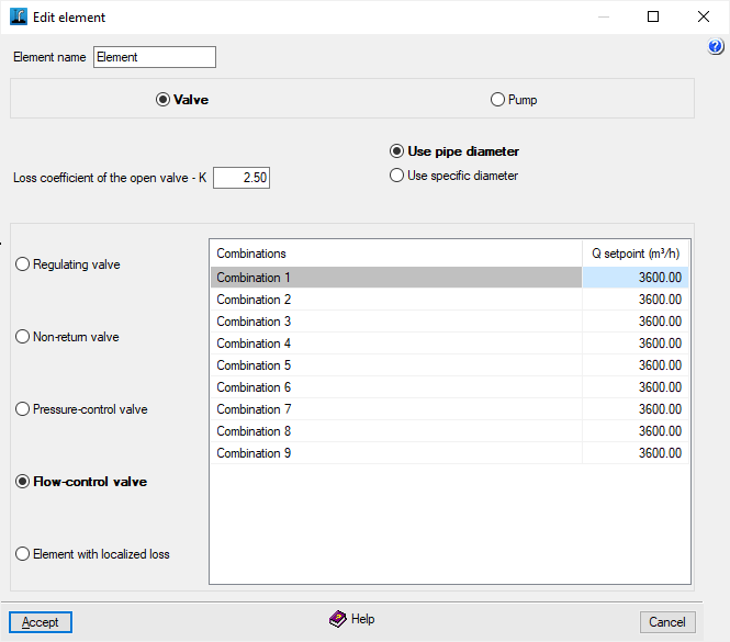
- Flow control valve
Its operation is similar to the previous one, but the setpoint is based on flow rate. Similarly, different flow settings can be defined for each combination. If the flow is less than or equal to the setpoint, only the losses associated with the valve being fully open will be taken into account.- Combinations, Setpoint pressure
- Element with localised losses
Allows you to simulate any special element, such as reducers, elbows, etc. It only requires the dimensionless loss coefficient, which is provided in the manufacturers’ catalogues.
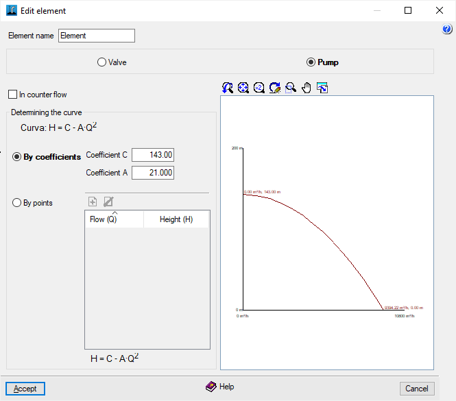
Editing pumps
- In counter flow (optional)
If the pump has not been installed with the correct flow direction, tick this box to ensure it operates correctly. - Determination of the curve (Curve H = C - A·Q²)
This can be defined in two ways:- By coefficients
The head H is given in metres of man-made water column (m.c.a.) and the flow rate Q passing through the pump in m³/s. The first coefficient of the pump curve (C) represents the head at zero flow. The second term (-A·Q²), which is always negative, represents the downward concavity of the curve.- C coefficient
- Coefficient A
- By data points
The data points must be entered in order of increasing flow rates and decreasing head to plot the pump performance curve. The program displays the fitted curve obtained using the least squares method. If the parameters obtained from the data points fall outside the normal limits, the pump curve will not be plotted on the graph.- Flow rate (Q), Head (H)
- By coefficients