
Adjustment and configuration tools in the "Beams" menu
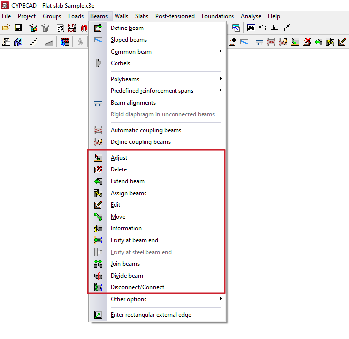
The program offers the following tools for adjusting and configuring beams in the "Beams" menu, within the "Beam input" tab:
- Adjust
- Delete
- Extend beam
- Assign beams
- Edit
- Move
- Information
- Fixity at beam end
- Fixity at steel beam end
- Join beams
- Divide beams
- Disconnect/Connect
Each of these tools is described below:
Adjust
The "Adjust" option allows you to adjust the position of a beam by aligning its faces or axis with the faces or axes of nearby columns or screens, as well as with lines from a DXF/DWG template, contours, maximum slope lines, or intersection lines of inclined planes.
- To adjust one end of the beam, left-click on it, moving the cursor close to the face you wish to adjust and keeping the cursor outside the beam.
- To adjust both ends of the beam at the same time, i.e. to adjust the entire beam, click on the centre of the beam, close to the corresponding face, and keep the cursor outside the beam.
- The adjustment can also be made to axes. To do this, left-click on the end or centre of the beam, keeping the cursor within the beam.
- If you want to adjust to a DXF or DWG template or to a contour, you must first select the "Capture to templates" option in the toolbar and, in the dialogue box that appears, choose the "Nearest" capture. When you do this, the "Fit" option will adjust the beams to the DXF or DWG template lines or contours and not to the faces or axes of columns, until the snaps are deactivated.
- If inclined planes have been defined previously, right-clicking the mouse will bring up a dialogue box with the option "Adjust to intersection of planes / lines of maximum slope". Activating this option allows the following:
- If two sloping floors are found on a beam, it is possible to adjust the beam to the intersection line of the two planes of these floors.
- If a beam is defined on an sloped plane, it is possible to adjust the beam to a line that passes through its centre and takes the direction of maximum slope of the plane or the direction perpendicular to the maximum slope of the plane, depending on which is closest to the current direction of the beam.
Delete
With the "Delete" option, you can remove any beam you have entered. You can remove a beam by clicking on it with the left mouse button or, after clicking the right mouse button, by entering the beam number in the dialogue box that appears.
If a beam is divided by another beam (for example, in the case of a beam supporting a roof truss), only the indicated section of the beam is deleted.
When deleting a beam that divides two panels, use the left mouse button to select the panel you wish to keep. After deleting the beam, this panel will cover the surface of the two previously existing panels.
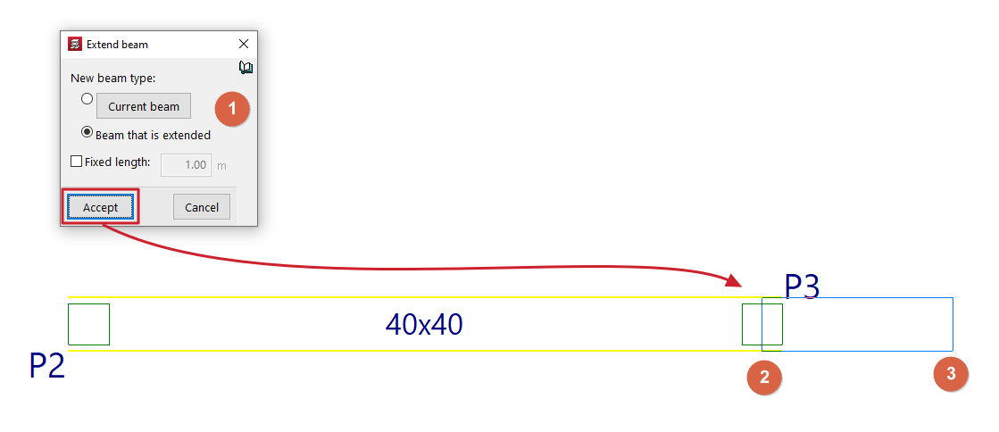
Extend beam
With the "Extend beam" option, you can move the end of a beam in the direction of its axis.
When you click on the option, a dialogue box appears where you must indicate the "Type of new beam" that will be applied to the extended section. This can be the definition applied to the "Current beam", which can be viewed and modified by clicking on the corresponding button, or the same data can be taken from the "Beam being extended".
If the "Fixed length" box is checked, the beam will be extended by the length indicated in the field provided for this purpose. To do this, when you hover the pointer over a beam in the floor plan, a preview of the extension will be displayed, which can be validated by clicking with the left mouse button.
If the "Fixed length" box remains unchecked, select the beam and then use the left mouse button to mark the new position of one of its ends on the floor plan.
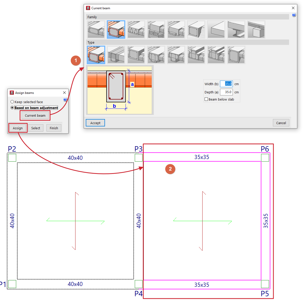
Assign beams
The "Assign beams" option allows you to copy the characteristics of the last beam entered (or current beam) to beam spans already entered in the model by selecting them in plan view. This allows you to change the data of existing beams without having to delete and re-enter them.
Clicking on the option opens a dialogue box with the following options:
- Keep selected face fixed
This option allows you to keep one of the faces or the axis of the beam fixed when assigning new dimensions. To do this, when selecting an individual beam, place the cursor on the outside of the beam and close to the face you want to keep fixed, or on the inside of the beam if you want to keep the beam axis fixed. This option cannot be used if multiple beams are assigned. - According to beam setting
This option allows you to maintain the original setting defined in the beam when assigning new dimensions, regardless of the position of the pointer when selecting the beam. This option can be used both in individual assignment to a beam and in multiple assignment to several beams.
The "Current beam" button allows you to view and modify the data for the current beam or the last beam entered, which will be assigned to the selected beams.
At the bottom, the "Assign" option allows you to select the beams in the plan to which the data will be assigned, while "Select" allows you to extract the information from a specific beam in the plan to define the current beam. The "Finish" option allows you to end the operation without changes.
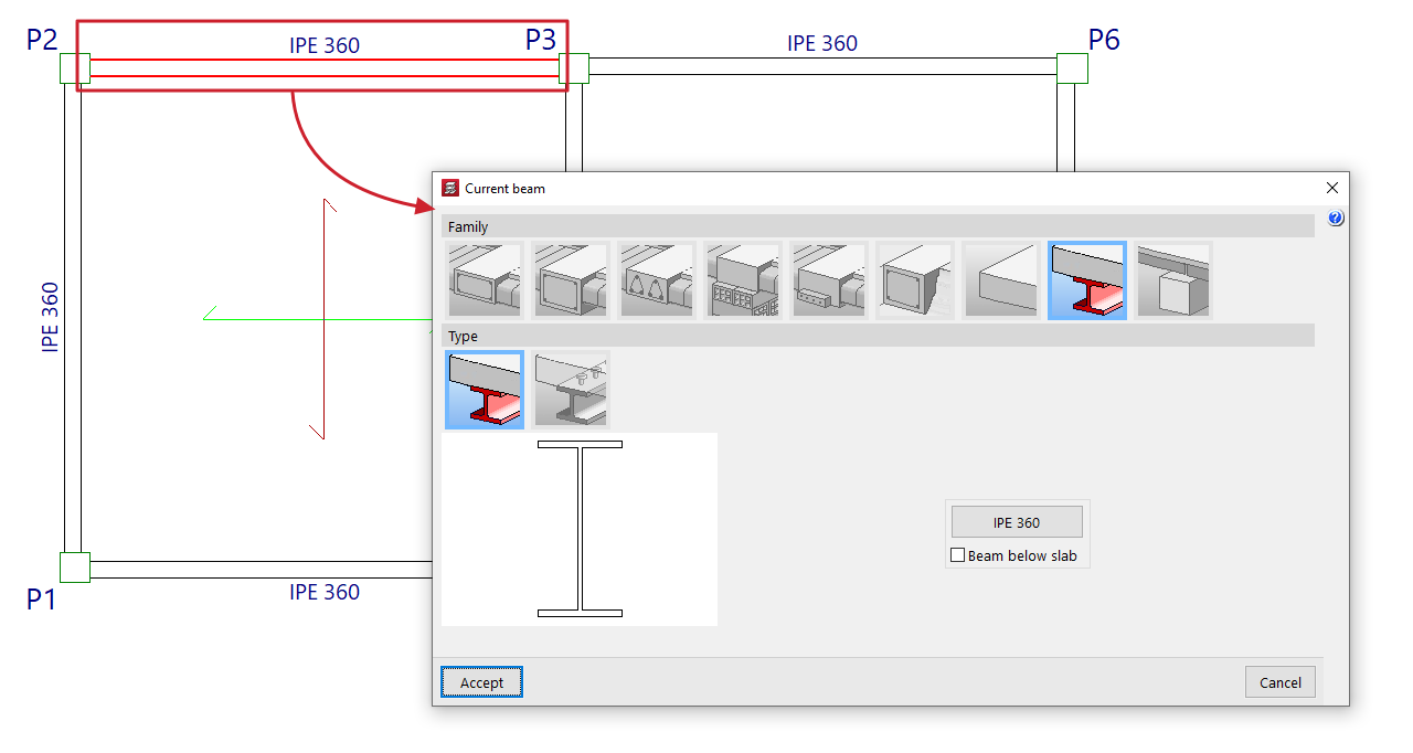
Edit
With the "Edit" option, you can edit and change the characteristics of the beam section selected in the floor plan.
The program will open the beam definition window so that you can enter the desired configuration, which will be applied to the beam when you click on "Accept".
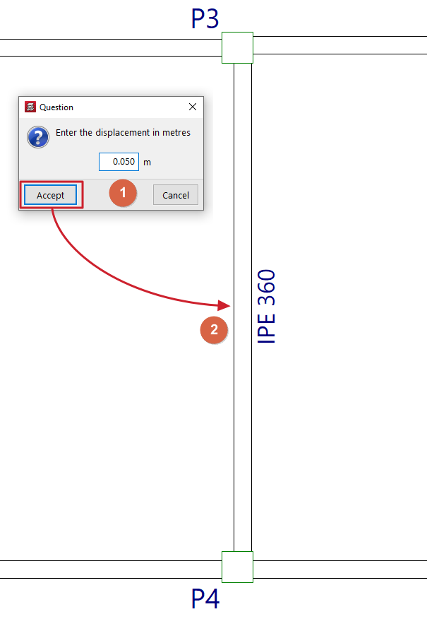
Move
With the "Displace" option, you can move the end of a beam (keeping the other end fixed) or move the entire beam in parallel, based on a defined displacement value.
When you select this option, the message line at the bottom of the program interface will display the value of the "Current offset" or offset that will be applied. You can change this value by right-clicking and entering the new offset value in the dialogue box that opens.
Next, to move the beam, place the cursor near the end or centre of the beam and click on the side towards which you want to move it, depending on whether you want to move only one end or the entire beam in parallel.
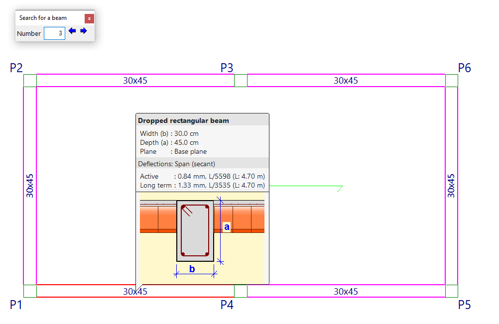
Information
The "Information" option allows you to display an information box on the screen about the characteristics and results of the beam selected in the plan.
To do this, select the beam with the mouse pointer, or type its "Number" in the corresponding field of the "Search for a beam" dialogue box that appears and press 'Enter'. When you do this, the beam will be marked in red and the rest of the beams that are the same as the selected beam will be marked in magenta.
If you click the right mouse button, or if you use the "Next beam" option in the dialogue box that appears, you will see the information for the beam following the current one. Similarly, the "Previous beam" option allows you to view the information for the beam with the number preceding the current one.
If the structure has been calculated, information about the deflections calculated for each beam will also be displayed. If any deflection limit is exceeded, its value will be shown in red.
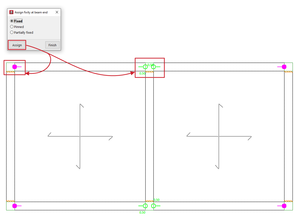
Fixity at beam end
This option allows you to assign the type of fixity at the ends of beams made of any material.
Clicking on it opens the "Assign fixity at beam end" window, where you can select the type of support from those available. This can be:
- Fixed
- Pinned
- Partially fixed
In this case, a value between 0 and 1 must be defined.
After selecting one of the above, click on "Assign" and select the end or ends of one or more beams by marking them one by one or using a capture area.
Each type of recess or joint is represented on the screen by a different symbol.
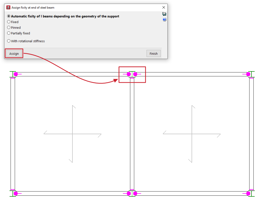
Fixity at the end of a steel beam
This option allows you to assign the type of fixity at the ends of the metal beams.
Clicking on it opens the "Assign fixity at end of a steel beam" window, where you can select the type of embedding from those available. This can be:
- Automatic fixity of I beams depending on the geometry of the support
This option is only available for I beams made of rolled or reinforced steel. When this option is selected, a hinge will be automatically assigned to the end of these beams if that end rests on the web of a column or another beam with a double T section. Otherwise, a fixed support will be assigned. - Fixed
- Pinned
- Partially fixed
In this case, a value between 0 and 1 must be defined. - With rotational stiffness
In this case, the rotational stiffness value must be entered at the end of the part. The program provides help in explaining the effects of "Consideration in the analysis model of rotational stiffness at the ends of parts".
After selecting one of the above, click on "Assign" and select the end or ends of one or more metal beams by marking them one by one or using a capture area.
Each type of recess or connection is represented on the screen by a different symbol.
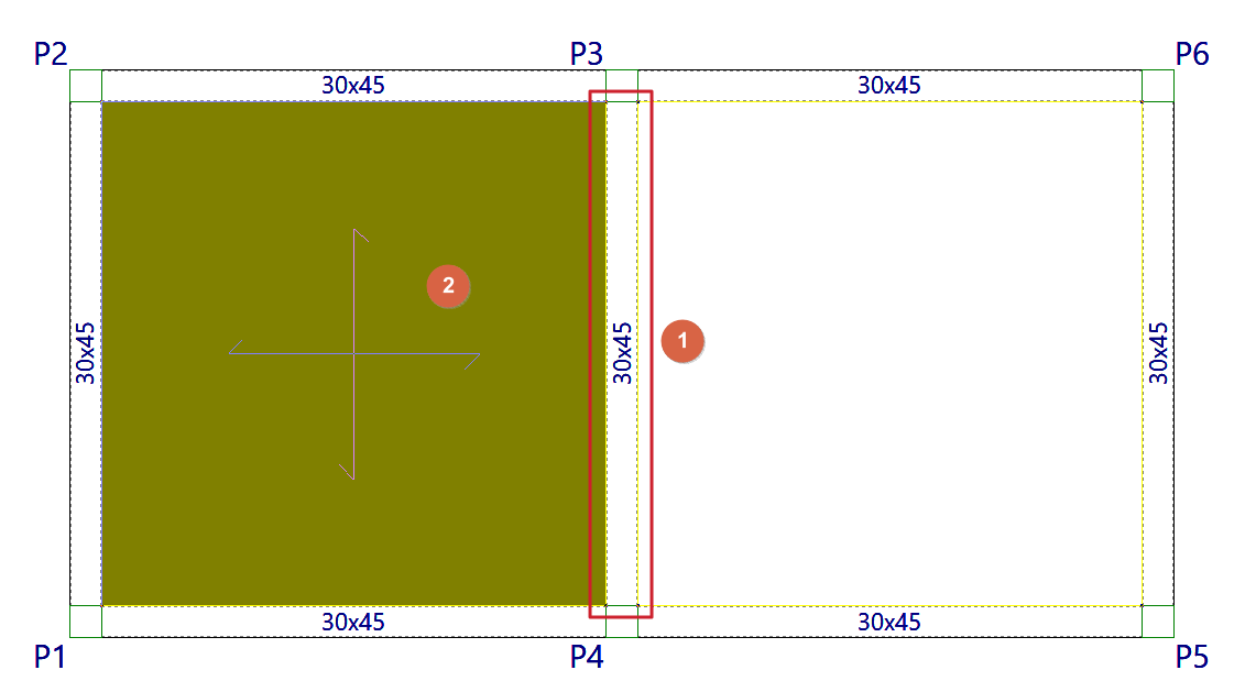
Join beams
The "Join beams" option allows you to join two aligned beams with matching ends and the same cross-section.
To do this, two sections of beams with these characteristics are marked on the floor plan using the left button.
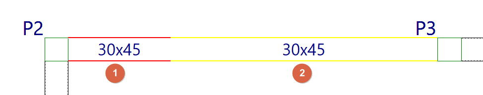
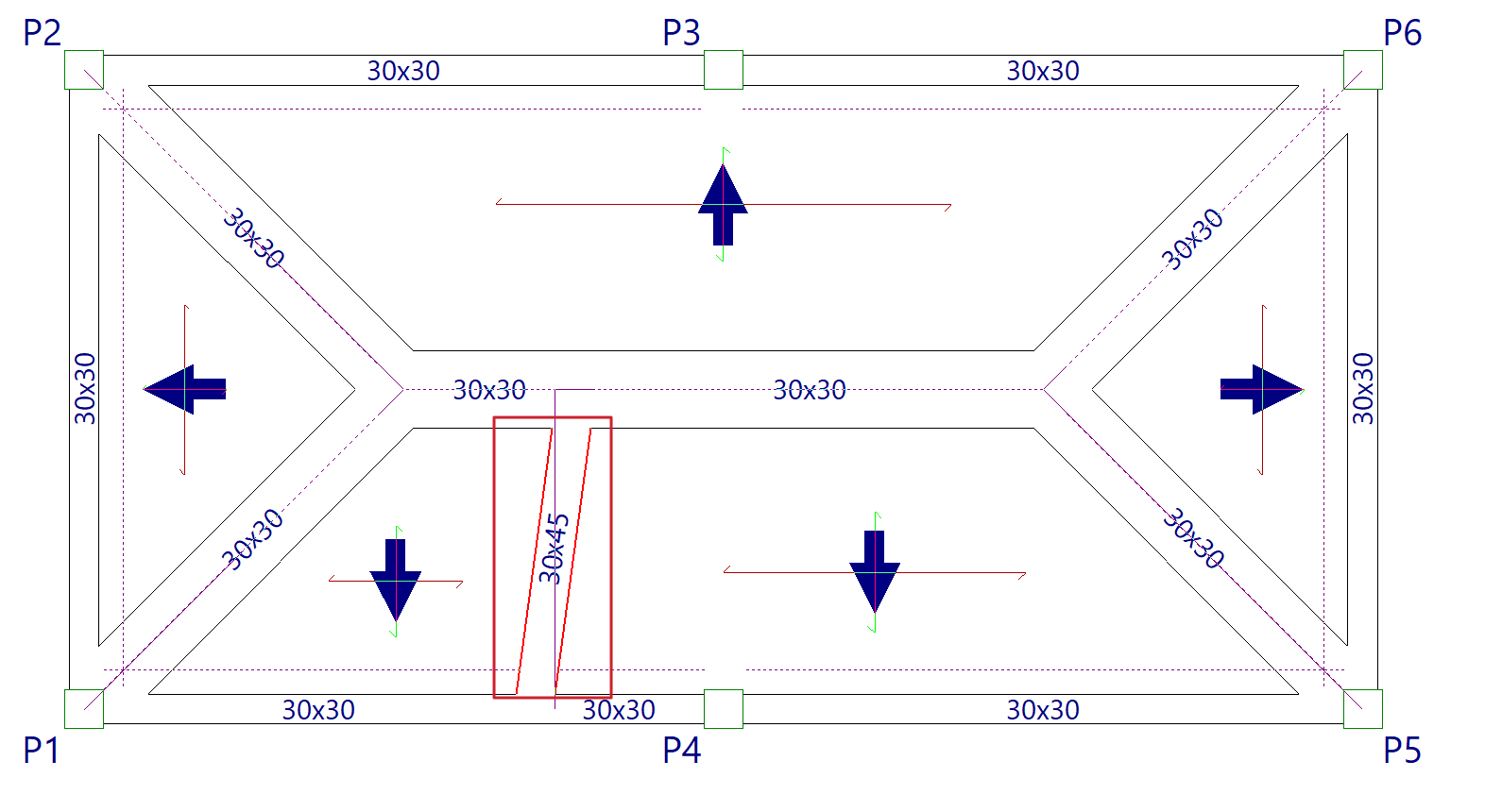
Divide beams
The "Divide beam" option allows you to split a beam into several sections.
To do this, after clicking on the option, mark the point on the beam where you want to make the division and click the left button.
Division may be necessary, for example, if a section change is desired.
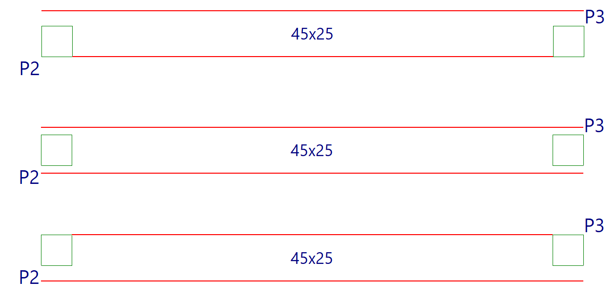
Disconnect/Connect
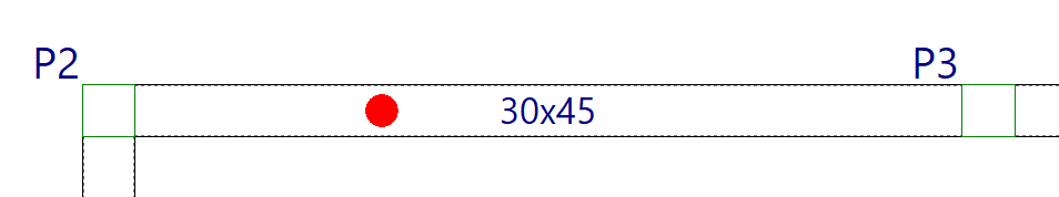
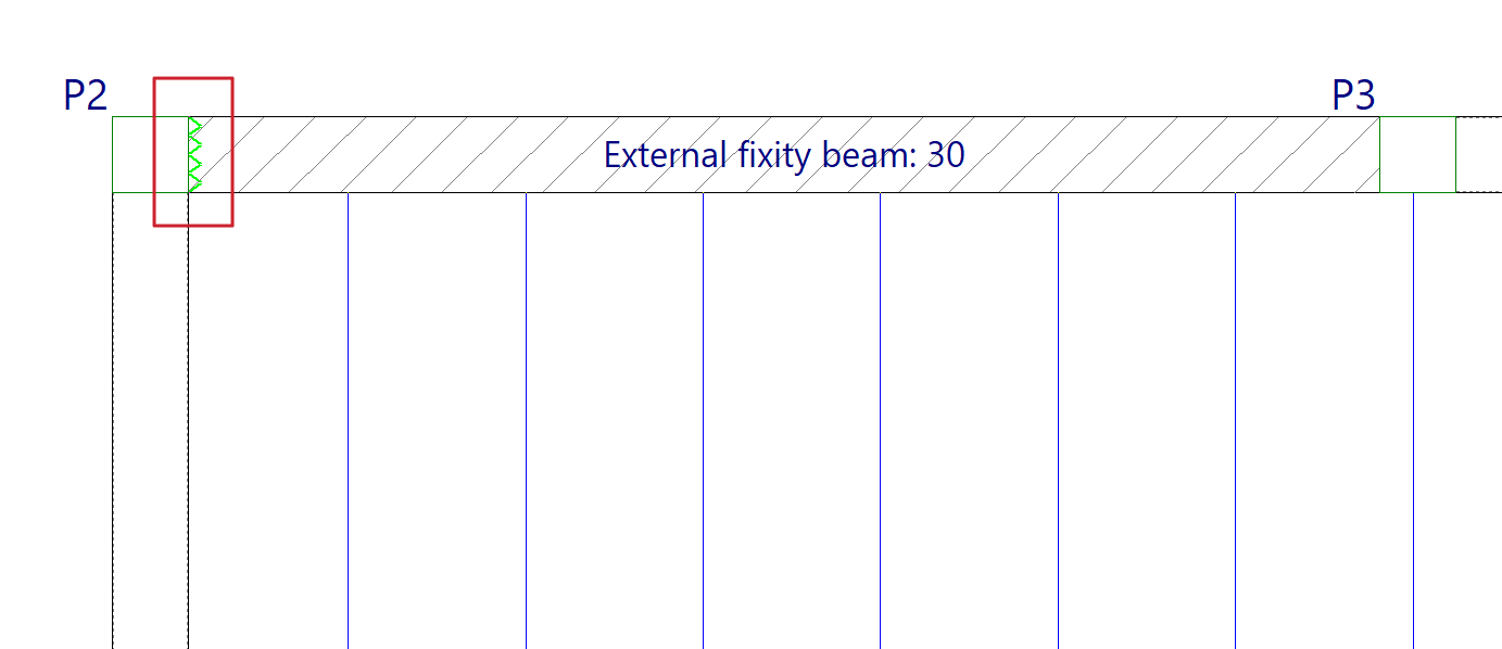
The "Disconnect/Connect" option allows you to disconnect or connect the ends of the "Beams with external connection" (entered from "Beams > Enter beam" and representing supports on piers, supports on walls or embedments) with the columns.
When disconnecting a beam with external connection from a column, the vertical movement of the column will not be impeded by this type of beam. The program will represent this disconnection by drawing a sawtooth symbol on the contact face of the beam with the column.
Otherwise, the beam with external connection will be connected to the column and the column's vertical displacement will be impeded by this beam.
| Note: |
|---|
| This disconnection of this type of beam from the columns is only effective in one-way slabs, since slabs and composite slabs are also connected directly to the columns, not only through the side beams. If this problem is encountered, it is advisable to use other types of designs, for example, by removing the beam with external connection and defining the wall element completely from "Walls > Enter wall". |