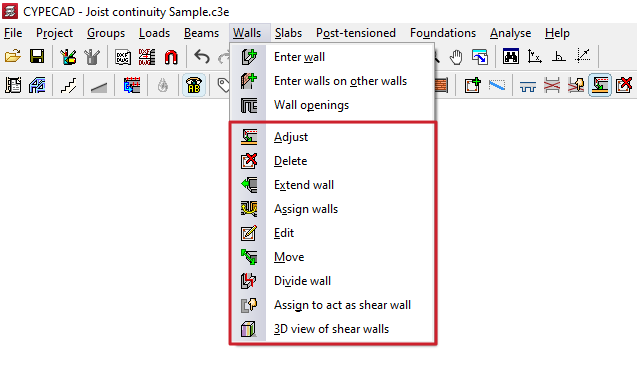
Adjustment and configuration tools in the "Walls" menu
The program offers the following tools for adjusting and configuring walls in the "Walls" menu, within the "Beam input" tab:
- Adjust
- Delete
- Extend wall
- Assign walls
- Edit
- Move
- Divide wall
- Assign to act as shear wall
- 3D view of shear walls
Each of these tools is described below:
Adjust
The "Adjust" option allows you to adjust the position of a wall by aligning its faces or axis with the faces or axes of nearby columns or screens, as well as with lines from a DXF/DWG template, contours, lines of maximum slope, or intersection lines of sloping wall sections.
- To adjust one end of the wall, left-click on it, move the cursor close to the face you wish to adjust, and keep the cursor outside the wall.
- To adjust both ends of the wall at the same time—that is, to adjust the entire wall—click in the centre of the wall, moving the cursor close to the relevant face whilst keeping it outside the wall.
- You can also adjust the axes. To do this, left-click on the edge or the centre of the wall whilst keeping the cursor inside the wall.
- If you wish to snap to a DXF or DWG template or to an outline, you must first select the "Template object snaps" option from the toolbar and, in the dialogue box that appears, choose the "Closest" snap. When you do this, the "Adjust" option will fit the walls to the DXF or DWG template lines or to the outlines, rather than to the faces or axes of columns, until snapping is disabled.
- If inclined planes have been defined previously, right-clicking will bring up a dialogue box containing the "Adjust to intersection of planes / line of maximum slope" option. Selecting this option allows you to do the following:
- If a wall is intersected by two sloping floor slabs, it is possible to align the wall with the line where the two planes of these floor slabs intersect.
- If a wall is defined on an inclined plane, it is possible to align the wall with a line passing through its centre that follows either the direction of the maximum slope of the plane or the direction perpendicular to the maximum slope of the plane, whichever is closest to the wall’s current direction.
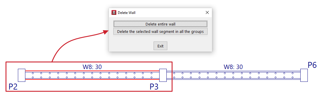
Delete
You can use the "Delete" option to remove any wall you have added.
If a wall is divided into several sections (for example, where a beam or wall meets another wall), clicking on a wall brings up a dialogue box with two options:
- Delete entire wall
This option deletes the entire selected wall, including all sections in all groups. - Delete the selected wall segment in all the groups
This option removes only the specified section of wall from all groups, leaving the remaining sections intact.
Extend wall
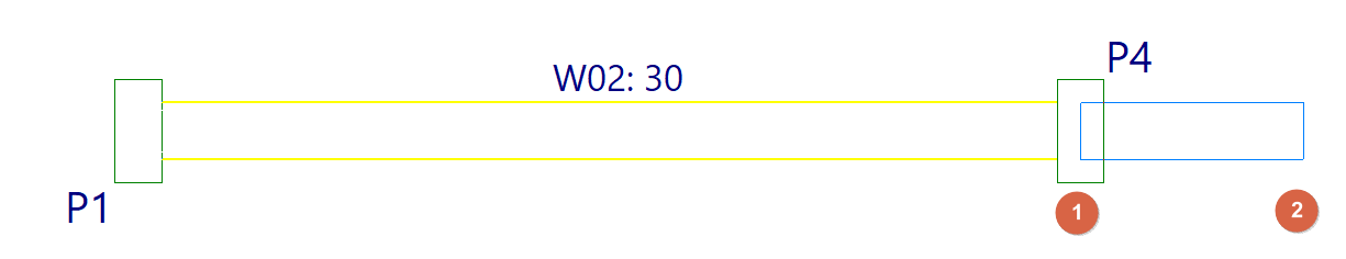
Using the "Extend wall" option, you can move the end of a wall along its axis.
Select the wall using the left mouse button in the floor plan view, then click the left mouse button in the floor plan to mark the new desired position for one of its ends.
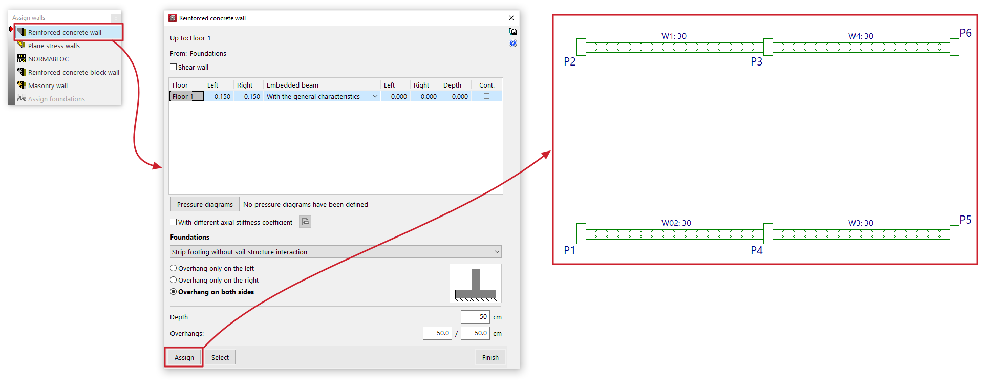
Assign walls
The "Assign walls" option allows you to copy the properties of the selected wall to other walls in the current group.
Clicking on this option opens a dialogue box where you can select the type of wall from those available ("Reinforced concrete wall", "Plane stress walls", "NORMABLOC", "Reinforced concrete block wall" or "Masonry wall") in order to configure the characteristics to be assigned.
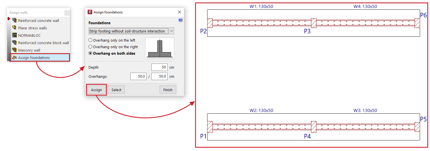
In addition, the "Assign foundation" option is available if any walls originate from the visible floor group. This option allows you to configure a wall foundation type that can subsequently be applied to the selected walls.
At the bottom, the "Assign" option allows you to select the walls in the floor plan to which the data will be assigned (whether the characteristics of the selected wall type or the configuration defined for its foundation), whilst "Select" allows you to extract the information to be assigned by selecting a specific wall in the floor plan. The "Finish" option allows you to complete the operation without making any changes.
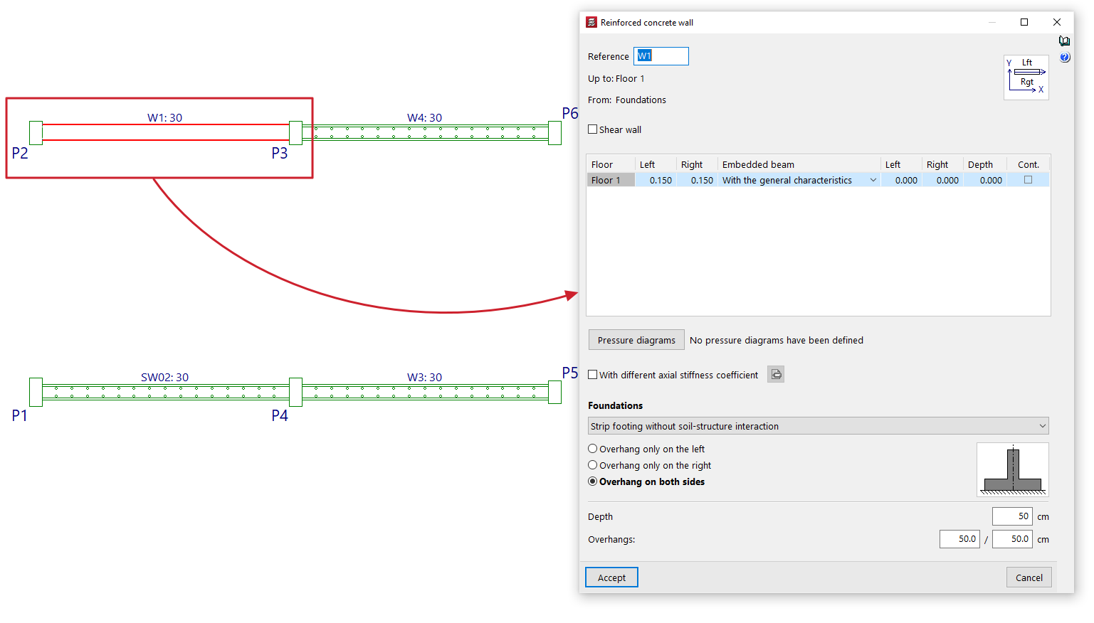
Edit
Using the "Edit" option, you can edit and modify the properties of the selected wall on the floor plan, as well as its foundations.
The program will open the wall definition window so that you can enter the desired settings, which will be applied to the wall when you click "Accept".
Move
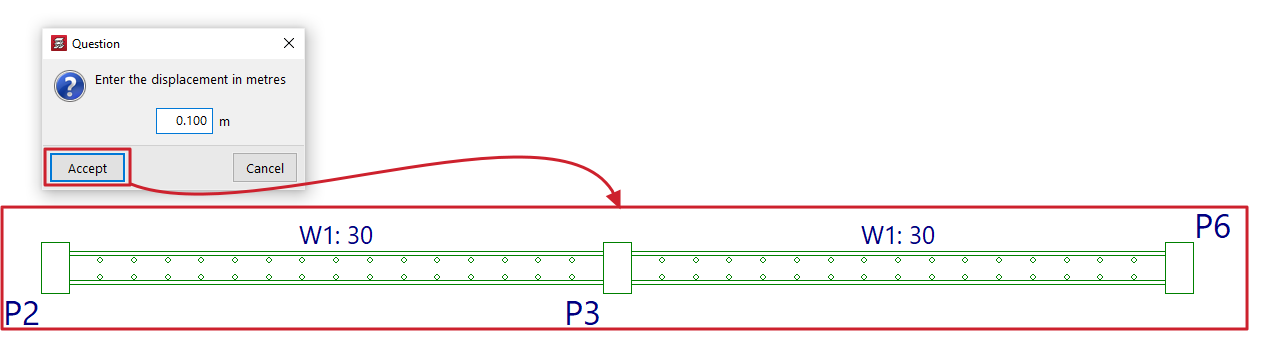
The "Move" option allows you to move one end of a wall (whilst keeping the other end fixed) or to move the entire wall in parallel, based on a specified displacement value.
When you select this option, the message bar at the bottom of the program interface will display the value for "Current displacement" – the displacement that will be applied. You can change this value by right-clicking and entering the new displacement value in the dialogue box that opens.
Next, to move the wall, place the cursor near one end or the centre of the wall and click on the side towards which you want to move it, depending on whether you want to move just one end or the entire wall in parallel.
Divide wall
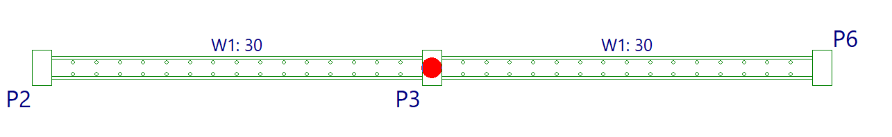
The "Divide wall" option allows you to split a wall into several sections.
To do this, after clicking on the option, select the point on the wall where you want to create the division and click the left mouse button.
A split may be necessary, for example, if you wish to change sections.
Assign to act as shear wall
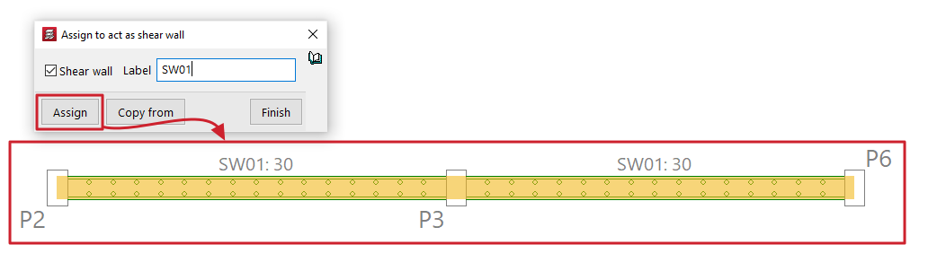
The "Assign to act as shear wall" option allows you to assign the shear wall function to one or more walls simultaneously.
Selecting this option opens a dialogue box where you must tick the "Shear wall" box and enter a "Label" for the wall. Clicking "Assign" will assign that label and the shear wall function to the selected walls on the floor plan.
Clicking on "Copy from" will allow you to extract the information from the selected wall on the floor plan, whilst "Finish" completes the operation.
All walls with the same label are grouped together to form a shear wall.
| Nota: |
|---|
| CYPECAD designs the reinforcement for shear walls by arranging the reinforcement to withstand the forces imposed by the applied forces. It does not perform specific checks for shear walls, nor does it generate the reinforcement layouts required by standards for this type of element. To design them correctly, you must link the job to a BIMserver.center project and, after exporting the results from CYPECAD, create a new file in the StruBIM Shear Walls program and link it to the same project. In the StruBIM Shear Walls program, you can design and verify reinforcement in accordance with all the requirements of the selected standard. |
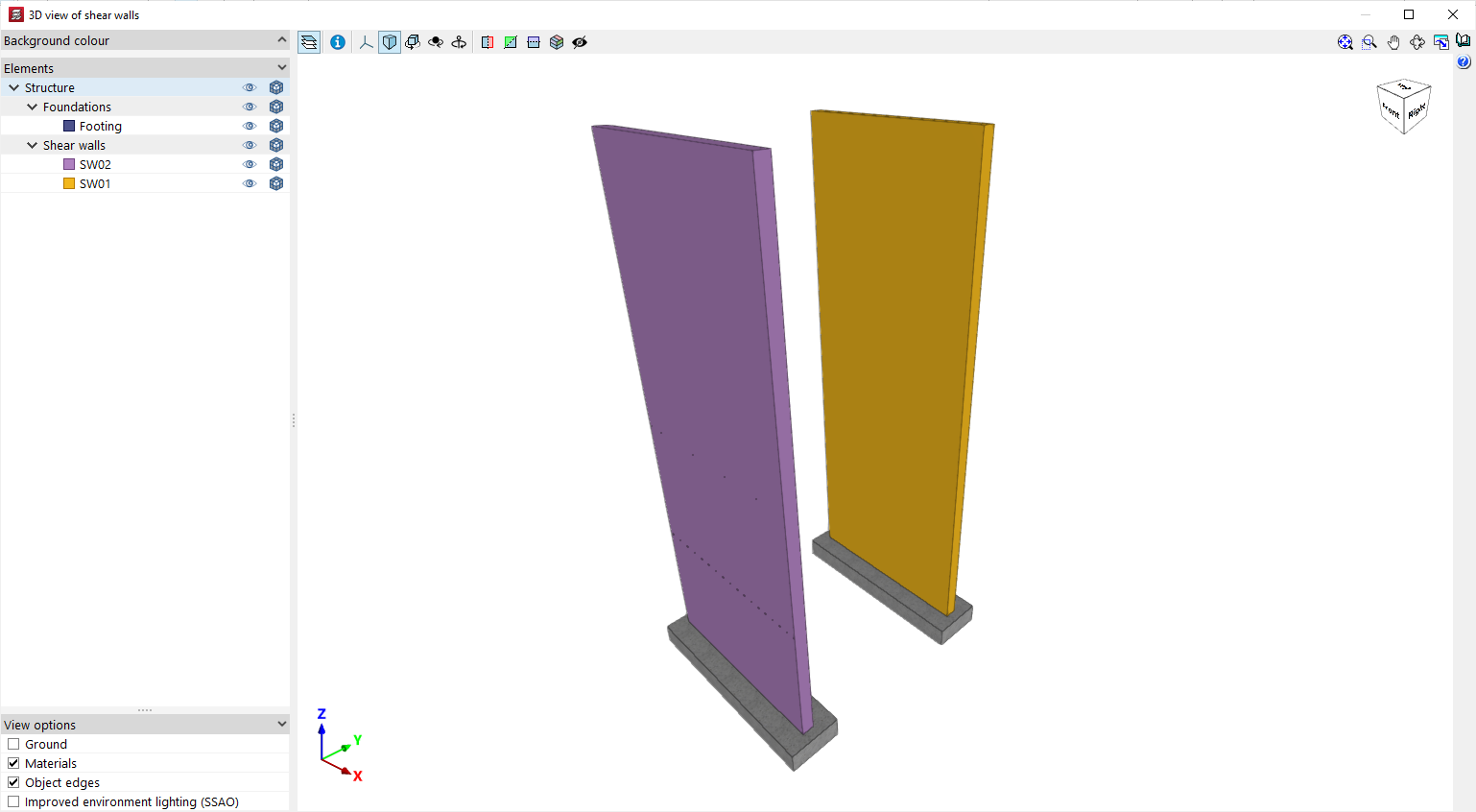
3D view of shear walls
Displays a 3D view of the reinforced concrete walls in the model. Each shear wall will be shown in a different colour to distinguish it from walls that have not been defined using the shear wall function.