

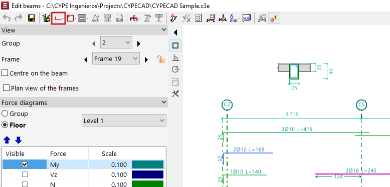
Editing longitudinal reinforcement of beams
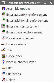
The editing tools for longitudinal reinforcement are located at the top of the beam editor window and include the following:
- Assembly options
- Enter assembly reinforcement
- Enter additional reinforcement
- Enter skin reinforcement
- Enter splice reinforcement
- Divide reinforcement
- Enter overlaps
- Join
- Divide pack
- Move to another layer
- Edit
- Edit bends
- Delete
These options are explained below:
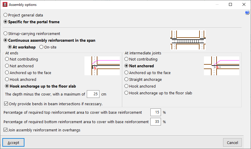
Assembly options
This option allows you to choose whether to use the general configuration for assembling reinforcement defined in "General project data" (Project > General data > By position > Beam options > Design / Check > Mounting reinforcement) or to use the options "Specific to the frame".
Enter assembly reinforcement
The "Enter assembly reinforcement" option allows you to select a beam that does not already have defined assembly reinforcement, or to define the initial and final nodes of the assembly reinforcement cage, as long as they are aligned.
Next, you specify the top and bottom reinforcement, the layout of the transverse reinforcement, and the bend definitions at the bar ends.
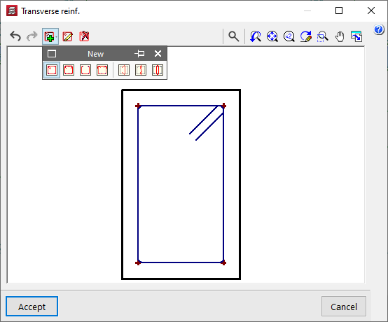
The program also allows you to "Import an admissible arrangement from the assembly reinforcement table" by clicking the button on the right. After selecting a row in the table, accept the panel.

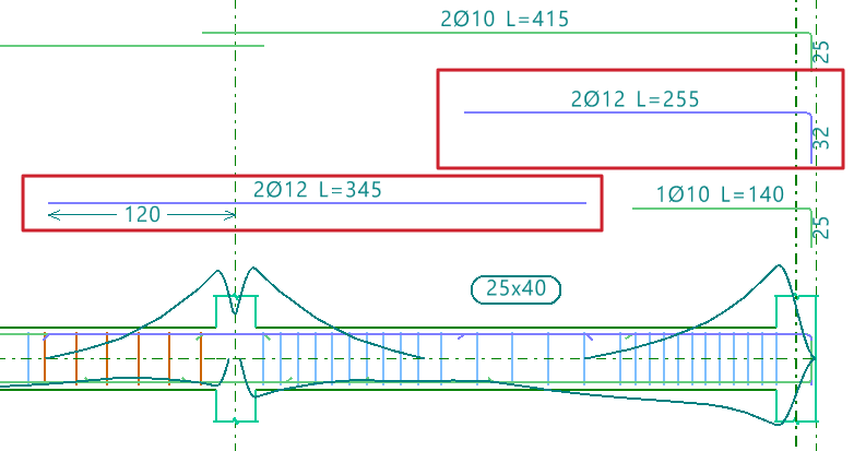
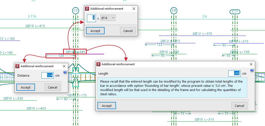
Enter additional reinforcement
To "Enter additional reinforcement", you define the number of bars and their diameter. Optionally, you can "Select the layer upon entering the reinforcement".

Then, position the pointer on the top or bottom of the frame, depending on where the reinforcement is to be placed, and click two points to define the spacing between the ends of the reinforcement bundle.

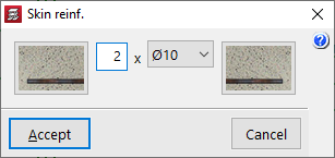
Enter skin reinforcement
To "Enter skin reinforcement", simply click on the beam and specify the number and diameter of the bars.
This reinforcement will be placed on both sides of the beam.

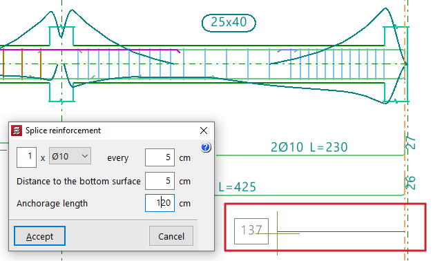
Enter splice reinforcement
To "Enter splice reinforcement", click one end of the beam, move the pointer inward across the span, and click again to indicate the "Distance" between bars.
Next, define the number and diameter of bars, spacing, "Distance to the bottom surface", and "Anchorage length".

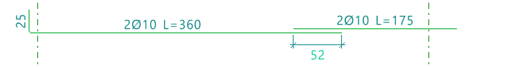
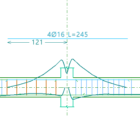
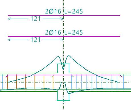
Divide reinforcement
The "Divide reinforcement" option allows you to select a point on a reinforcement bar and introduce a lap, splitting the bar into two bundles.
In the "Lap layout" section of the dialogue box, you can select the lap type:
- Lap centred on the selected cut point
- Lap to the left of the selected cut point
- Lap to the right of the selected cut point
At the bottom, you specify the "Lap length".

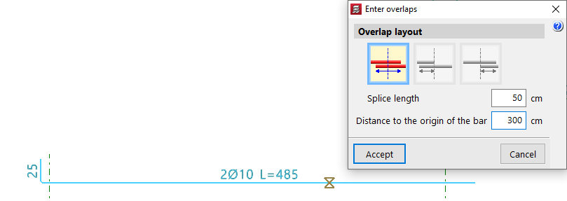
Enter overlaps
The "Enter overlaps" option allows you to select a point on a reinforcement bar and enter a lap without splitting the reinforcement group.
As with the previous option, in the "Lap layout" section, you can choose:
- Lap centred on the selected cut point
- Lap to the left of the selected cut point
- Lap to the right of the selected cut point
You also define the "Lap length", and additionally, the "Distance to the origin of the bar".
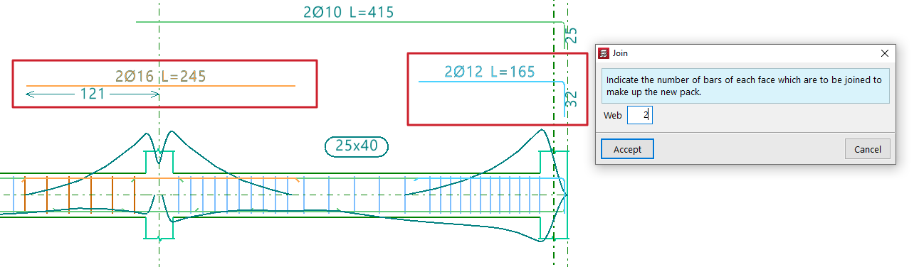
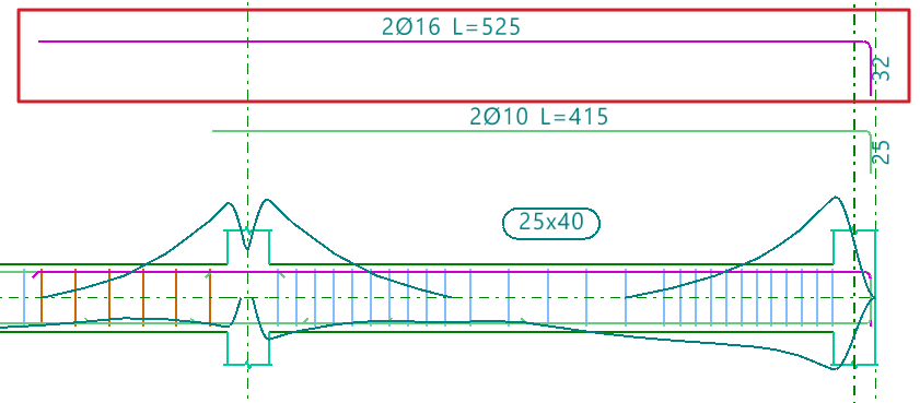
Join
The "Join" option allows you to combine multiple reinforcement bundles of the same type and face into a single one.You must specify the number of bars that will form the new bundle.
The program will take the diameter from the first selected bundle.
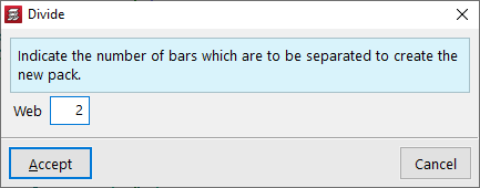
Divide pack
The "Divide pack" option allows a reinforcement bundle containing at least two bars to be divided into multiple bundles, enabling independent editing.
You must specify how many bars will be separated to form the new pack.
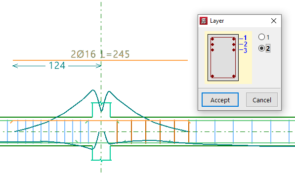
Place in another layer
The "Place in another layer" option allows you to select one or more reinforcement bundles and, after right-clicking, specify the layer where they will be placed.
These changes are evident in the beam's cross section. The program also considers the reduced lever arm in design checks when these changes are made.
Edit
The "Edit" option allows direct modification of reinforcement bars displayed in the main viewer after calculation.
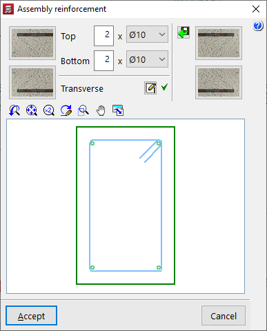
Editing assembly reinforcement
Clicking on the assembly reinforcement lets you adjust the number of bars and select their diameter for both the "Top" and "Bottom" layers.
You can also modify the "Transverse" reinforcement by clicking the corresponding button. In the resulting window, you can edit the Type of stirrup or "Type of branch", add stirrups or branches of different types by clicking on the longitudinal bars in the graphic, or "Delete reinforcement".

Editing additional reinforcement
To edit additional reinforcement, click on the descriptive labels of the bars in the main viewer. You can modify the number and diameter of bars, their Length, and the Distance between them, as well as the length and type of "Bend" if an end is selected.
When hovering near a bar’s end, a double arrow appears. Clicking it allows you to lengthen or shorten the bar. The program displays the bar’s total length on screen during this adjustment.
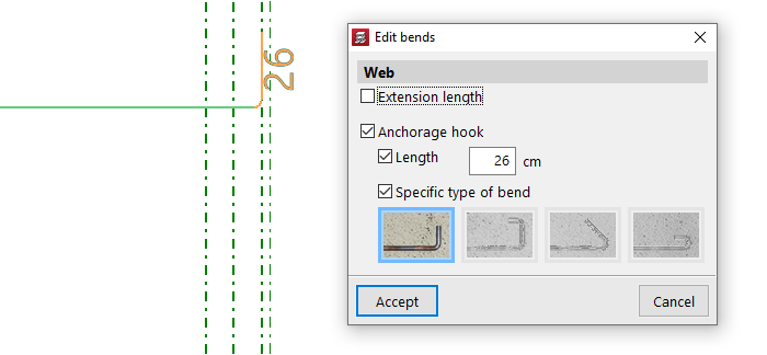
Edit bends
The "Edit bends" option allows you to modify bar hooks. All bends in the frame can be selected by drawing a selection box over it.
You can set the "Length" and select a "Specific type of bend" from the following:
- 90º bend
- 90º bend with horizontal extension
- 135º bend
- 180º bend
Delete
To delete reinforcement, use the "Delete" option and click on the reinforcement to remove it.
Verification, checks and saving changes

After making any reinforcement modifications, click the "Update error information" option in the top toolbar to verify the frame after the changes.
Once this is done, you can use the "U.L.S. and S.L.S. checks at the worst case point" and "U.L.S. and S.L.S. checks at a point" options to view the check reports and examine the results of your changes.
Finally, you can "Save" your work on the frame using the corresponding option.
If you want to exit the editor without keeping the changes, you can close the editing window and confirm in the dialogue box that appears.