

Automatic entry of projects: DXF, DWG and CAD/BIM models
The "Automatic entry" module in CYPECAD can generate the structure automatically in two ways:
- Importing IFC-format files generated by CAD/BIM software.
- Interpretation of data contained in DXF and DWG files.
In both cases, the structure is generated automatically following the intervention of a wizard that asks the user to confirm or complete the data contained in these types of files.
Importing IFC files from CAD/BIM software
The “Automatic entry” module allows files in IFC format generated by the leading CAD/BIM programs (Allplan®, Archicad®, Revit® Architecture) to be imported into CYPECAD. Using a wizard, the user confirms and completes the information extracted from the IFC file, after which the selected structural elements are automatically generated. The information that can be extracted from an IFC file (if the file contains it) may include:
- Floor height
- Floor loads
- Columns
- Beams forming external perimeters and internal openings
- Foundations
- Linear loads on partition walls and external walls
- Drawing templates for each floor
The IFC automatic input wizard features a series of sections which display or request the data that will automatically generate the project.
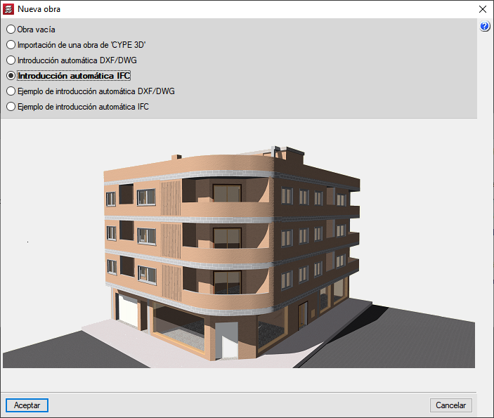
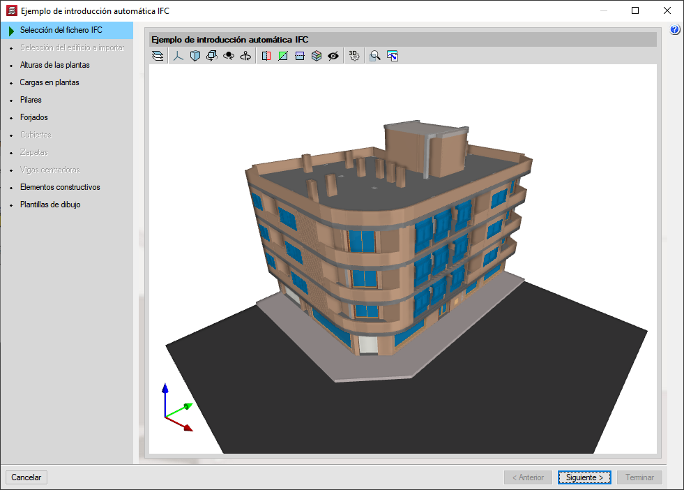
Selecting the IFC file
In this section, users can specify the location of the IFC file, from which the program will import the data displayed in the subsequent stages of the automatic input process.
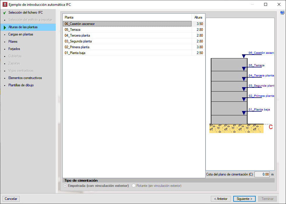
Floor height
This section defines the levels of all the floors contained in the selected IFC file. CYPECAD suggests the levels and names of the floors contained in the IFC file. The user can validate or modify this data. The type of foundation – deep (with external connection) or raft (without external connection) – and the elevation of the foundation plane are also specified here.
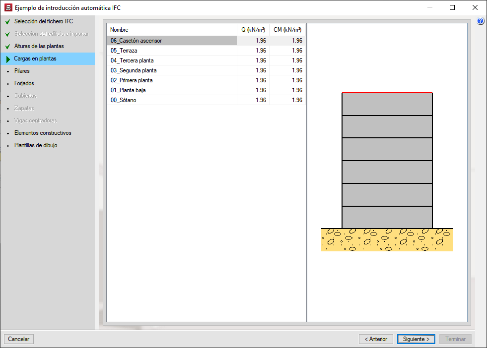
Floor loads
Here, users specify the live loads and dead loads for the structures contained in the selected IFC file.
Columns
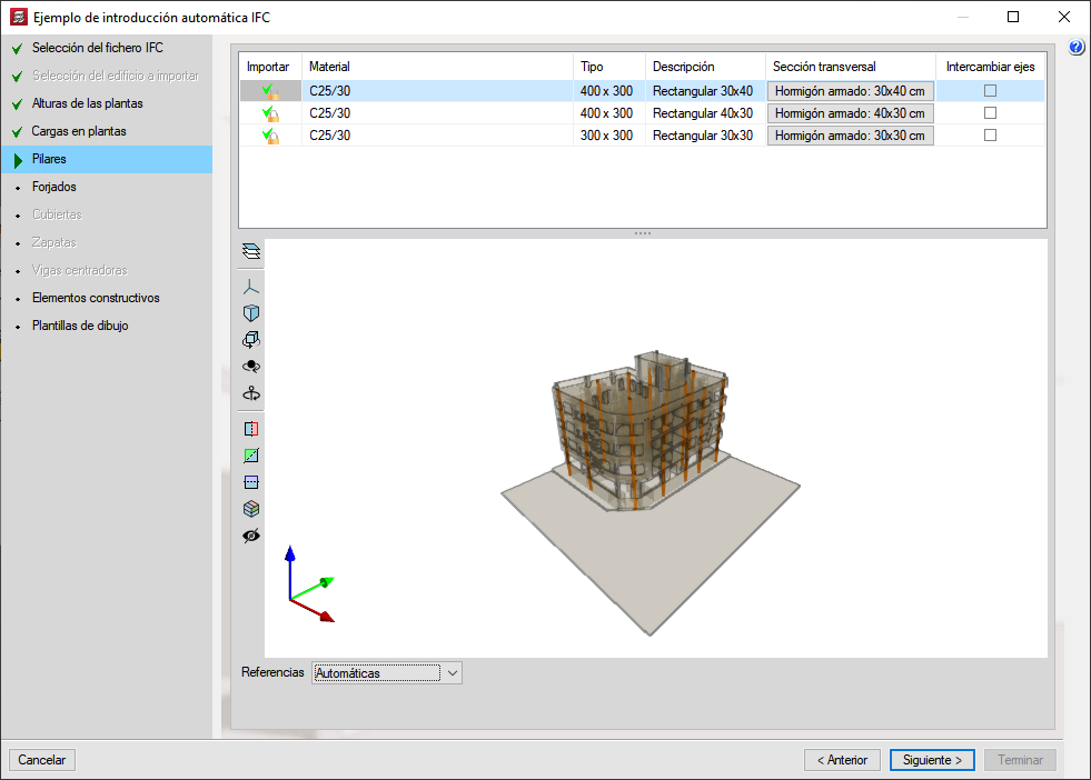
This section displays a list of column-type elements (IFCCOLUMN entity) contained in the IFC file. Users can select the ones they wish to import in order to generate the structural columns for the project.
Floor slabs
This section displays a list of the floor slab and roof elements (IFCSLAB and IFCROOF entities) contained in the IFC file. Users can select the floor slab and roof types they want CYPECAD to generate as external and internal outlines (openings). They must also select the beam types to be used to generate these outlines.

Building elements
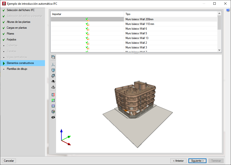
This section displays a list of elements of walls and partition walls (IFCWALL and IFCWALLSTANDARDCASE) contained in the IFC file. Users can select the walls and roofs for which they wish to obtain load data, so that these loads can be automatically applied as linear loads on the floor plans in CYPECAD.
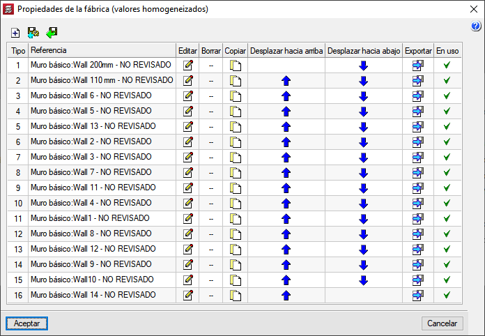
CYPECAD calculates the values of the linear loads based on the dimensions of the selected walls and partition walls, and on the surface weights chosen by the user from a dialogue box detailing the composition and surface weight of various types of walls and partitions. A generic type may be selected, in which case a surface weight must be assigned to it.
Drawing templates
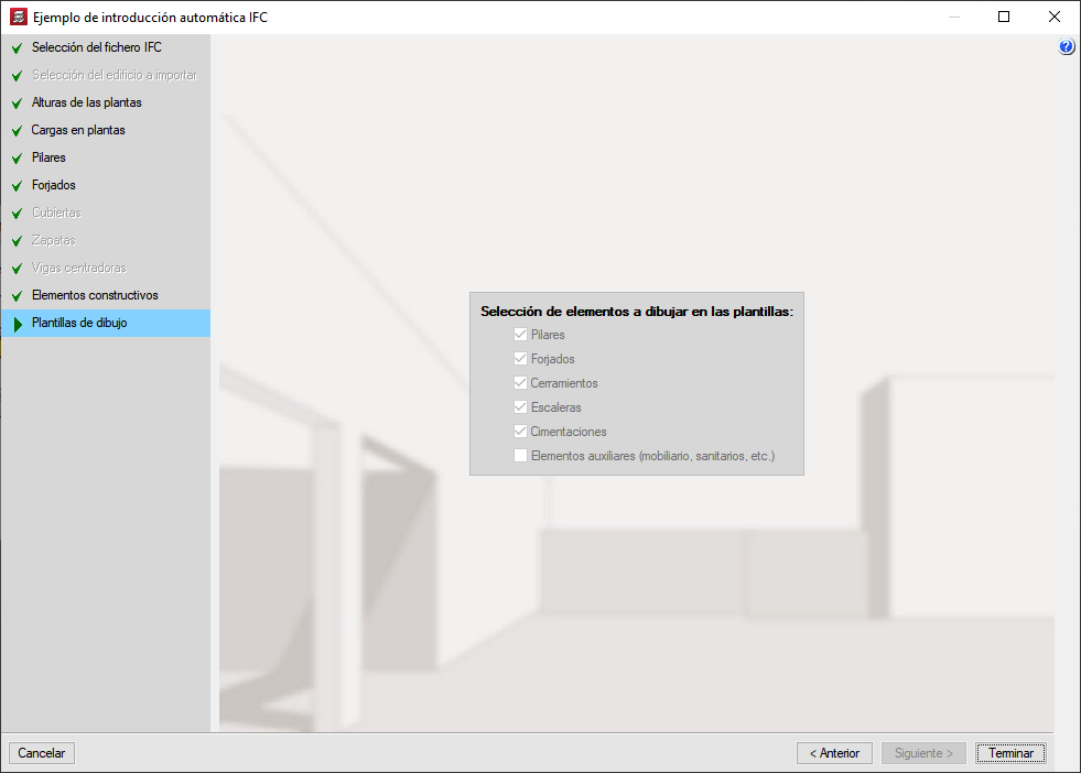
In this section, the user can enable the automatic creation of drawing templates to add them to the CYPECAD project with the elements selected here: columns, floor slabs, external walls and auxiliary elements. One template is created per floor.
The selection of auxiliary elements is not enabled by default. The user can enable it, but this will likely result in a drawing template containing too much information and, consequently, large files.
The IFC file may contain an element which, in the CAD/BIM program, was originally defined as a column, floor slab or roof (IFCCOLUMN, IFCSLAB or IFCROOF) but which is not actually a structural element and, therefore, should not be imported into CYPECAD. A similar situation applies to loads from external walls or partition walls. There is no need to generate loads for internal partition walls if they are included in the dead loads for each floor.
For this reason, the IFC automatic import wizard allows the user to select the elements they wish to import from the "Columns", "Floors" and "Structural elements" sections.
In the 3D views of the structure displayed in the "Columns", "Floors" and "Structural elements" sections, the elements that CYPECAD reads from the IFC file are shown in different colours. You can find information on the meaning of these colours in the FAQ section of our website, specifically in the question: What do the colours of the different elements that appear in the 3D views of some sections of the assistant for automatically inserting files in IFC format represent?
Importing DXF and DWG files
CYPECAD’s “Automatic entry” module can also import files in DXF and DWG formats in order to automatically generate the structure of the building (floor plans, general loads, columns, perimeter beams and interior span beams), based on the parameters specified by the user via a wizard.


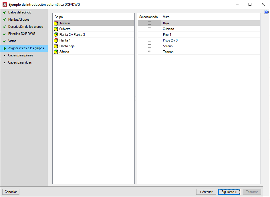

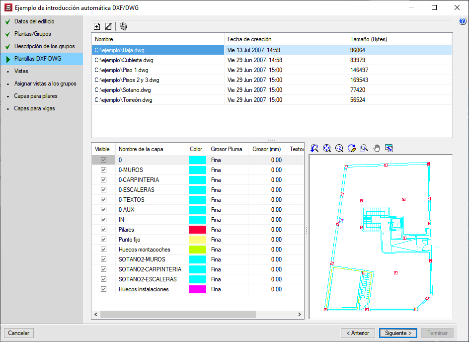
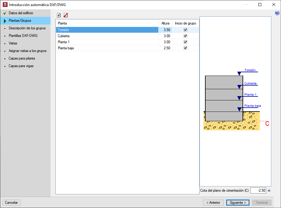


Users define the configuration of the building’s floors (basements, ground floor, storeys, roof, machinery slab, rooftop structure, etc.). Except for the ground floor and the roof, the remaining floors are optional. The heights, imposed loads, and dead loads for each floor are also specified.
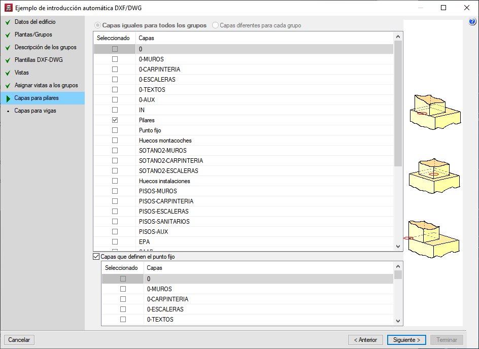
Next, select the DXF or DWG files for the structure and define the layers representing columns, external contours and opening contours.
The type of beams used to form the external and internal contours can be selected, and it is even possible to optionally define an offset of the beam relative to the contour line. This is particularly useful if the contour drawn in the DXF or DWG file represents the façade edge rather than the structural edge.
Using all this information, the program automatically generates the structure’s geometry (columns and beams); it even calculates the fixed points of the columns if their dimensions differ on each floor as defined in the supplied DXF or DWG files. Users can also specify a layer containing the definition of fixed column points so that these are not calculated automatically.
Once the column and beam geometry has been entered, users can make any manual adjustments to the generated structure, position the floor slabs and complete the structure definition.
If users have the “Automatic entry” module, they have the additional option of “Beam entry with the help of 'DXF' or 'DWG' drawing files” when entering beams manually. This option can be used during manual beam entry and allows any type of beam to be assigned to a polyline or line in the DXF or DWG file on any floor plan. The polyline may consist of straight and curved lines, and may be closed or open. This eliminates the need to enter the polyline geometry beam by beam.
Export in IFC format
CYPECAD can also export your project in IFC format. To do this, your license does not need to include the "Automatic entry" module. Further information on this can be found in the "Exporting in IFC format" section on the CYPECAD website.
Other features
To access the other features offered by the program, there are several modules available; you can find out more about them on the "CYPECAD modules" page.
