Beam entry
To enter beams in CYPECAD, open the "Beam input" tab and move to the required group using "Move up group", "Go to group" and "Move down group".
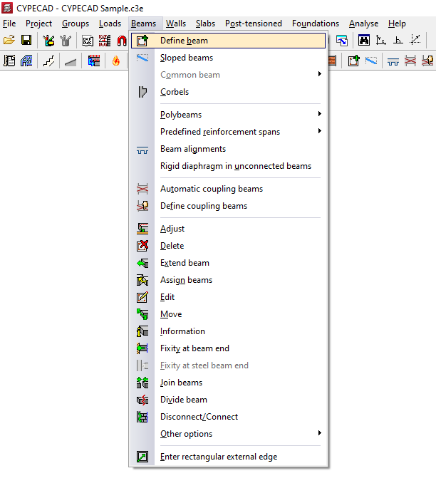
Then, in the "Beams" menu, select "Enter beam".
Selection of the current beam
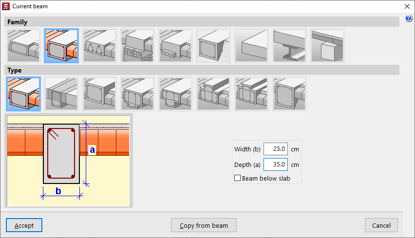
The program displays the "Current beam" window, where you can define the "Family" and "Type" of the beam to be entered, as well as its dimensions and properties.
The available families include:
- Flat beams
- Downstand beams
- Truss beams
- Beams with external restraint
- Prestressed beams
- Foundation beams
- Non-structural ring beam or boundary
- Steel beams
- Timber beams
All the values described above can be taken from an existing beam by clicking "Copy from beam" and then selecting another beam in the project with its information already defined.
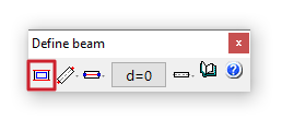
You can also access this window later by clicking the first option in the dialog box that appears while entering the beam, "Selection of the current beam".
Selection of the beam entry mode
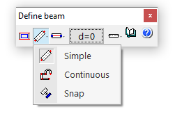
After confirming the beam type selection, choose the "Selection of the beam entry mode" from the drop-down list.
- "Simple" mode allows you to enter beam spans one by one by clicking on the start or end point.
- "Continuous" mode allows you to enter a sequence of beam spans through successive clicks. To finish, right-click and select "Finish entry". You can also "Delete last point" or "Delete all".
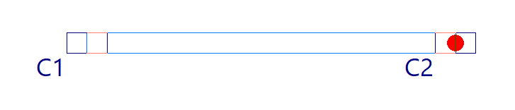
- "Snap" mode automatically converts a polyline or line from a DXF or DWG template into a series of CYPECAD beams by clicking on it. Depending on the pointer position, the beam is entered centred on or offset to one side of the selected line.
In the first two modes, you can use automatic snapping to previously entered columns and beams, as well as the "Template snaps" available from the corresponding button on the top toolbar.
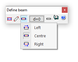
Selection of the alignment
The "Selection of the alignment" button allows you to specify whether the beam is placed at the "Centre", "Left" or "Right" of the entered line.
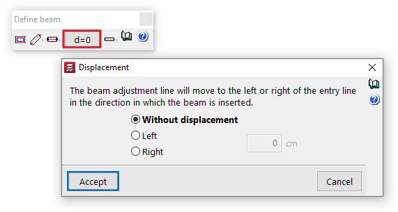
Displacement
The "Displacement" option allows you, during beam entry, to shift the alignment line by a specified distance to the left or right of the entry line, always in the direction of beam insertion.
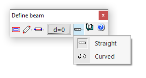
Straight and curved beam spans
The "Entry mode" option allows you to enter straight beam spans ("Straight") or "Curved" spans to model curved beams. In the latter case, in addition to the start and end points of the span, you must click a point along the arc to define the curved segment.
Beam layout in plan
Once the beam definition is complete, click "Accept". At this point, depending on the selected entry mode, you can move the pointer over other elements such as columns and beams to snap to them. You can also use snaps to previously entered templates.