Entering columns
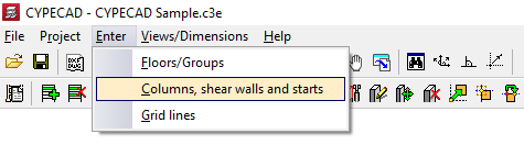
To enter columns in CYPECAD, within the "Column entry" tab, open the "Enter" menu and select the "Columns, shear walls and starts" option.
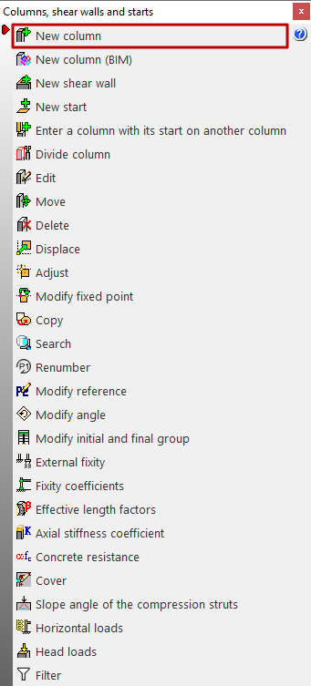
This opens a menu with the following options:
- New column
- New column (BIM)
- New shear wall
- New start
- Enter a column with its start on another column
- Divide column
- Edit
- Move
- Delete
- Displace
- Adjust
- Modify fixed point
- Copy
- Search
- Renumber
- Modify reference
- Modify angle
- Modify initial and final group
- External fixity
- Fixity coefficients
- Effective length factors
- Axial stiffness coefficient
- Concrete resistance
- Cover
- Slope angle of the compression struts
- Horizontal loads
- Head loads
- Filter
The first of these features is detailed below.
New column
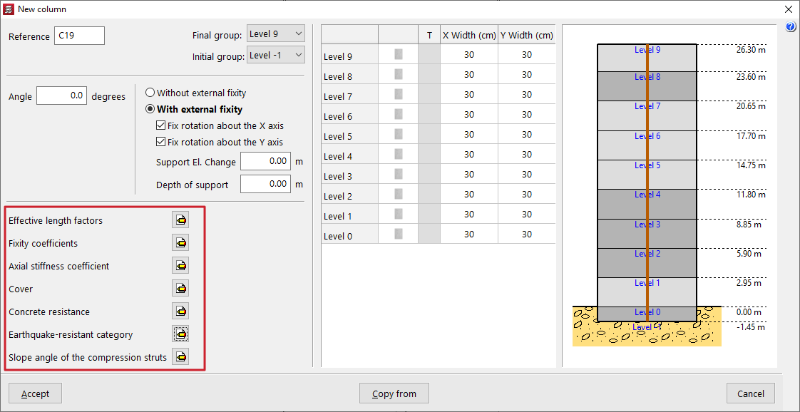
The "New column" option allows you to insert a column. The model must have more than one floor or group of floors for this option to be visible, as columns in the program must start and end in two different groups of floors.
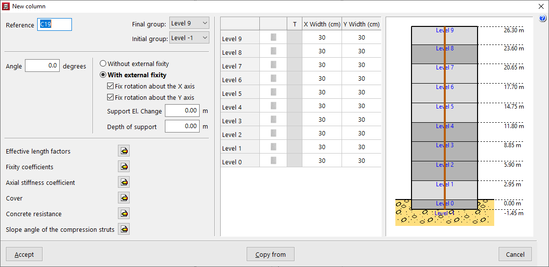
After selecting the option, the "Reference" of the column is entered and the "Final group" and "Initial group" are defined using the drop-down lists. The diagram on the right-hand side can help to visualise the floors of the model and the position of the column being inserted with respect to them.
An "Angle" can also be applied, which will rotate the column in plan.
"With external fixity" must be selected if the column starts on a pad footing or a pile cap, and "Without external fixity" if the column starts on a mat foundation, a foundation beam, a wall, or if it is supported on a beam or slab of the structure.
Optionally, the "Fix rotation about the X axis" and "Fix rotation about the Y axis" checkboxes can be deactivated so that rotation in that direction is not restrained. In this case, the beams in contact with the base of the column will contribute to centring the loads.
In "Support elevation change", a positive or negative value can be entered to modify the position of the base of the column with respect to the level of the group from which it starts.
The value of the "Depth of support" is used to indicate the depth of the foundation, which allows the program to correctly measure and draw the reinforcement of the column starters. If pad footings or pile caps are inserted in the program, it is not necessary to change this value, and it can be left as 0.
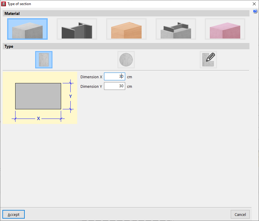
Column section
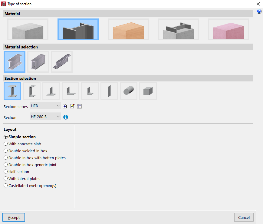
In the table on the right, the section of each column section is defined, floor by floor. To modify the "Section type", click on the buttons available in the second column. In the "Material" section, you can choose whether the column is "Reinforced concrete", "Steel", "Timber" or "Composite section". You can also define a column with generic material and section ("Generic").
In the case of steel columns, after accepting, you can activate the transposed steel section box (columns "T") to swap the axes of the section and thus rotate the column in plan.
In the case of rectangular concrete columns, the columns "Width X" and "Width Y" allow you to quickly modify these parameters.
Column parameters
In the lower left corner, you can modify the following parameters if desired:
- Effective length factors
- Fixity coefficients
- Axial stiffness coefficient
- Cover
- Concrete resistance
- Earthquake-resistant category
- Slope angle of the compression struts
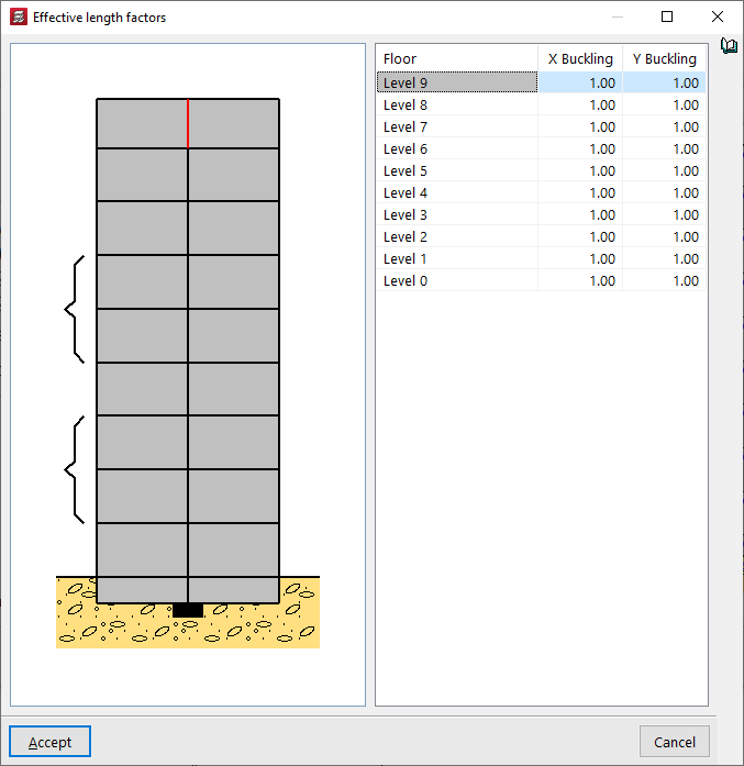
Effective length factors
By default, the value of the "Effective length factors" is 1 in both directions. It is possible to increase or decrease the "X Buckling" and "Y Buckling" coefficients by entering the desired value in the corresponding cell.
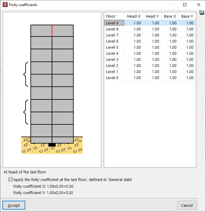
Fixity coefficients
The value of the "Embedding coefficients" is 1 by default, but it can be reduced to decrease the embedding or simulate a joint, both at the head and foot of each section of the column and in both directions of space, X and Y.
If the "Apply the embedding coefficient on the top floor, defined in "'General data'" box at the bottom remains active, the embedding coefficient in X and Y of the head of the upper section of the column indicated in the table will be multiplied by this value, which by default is equal to 0.30.
| Note: |
|---|
| This coefficient is defined in "Project" > "General data" > "By position" > "Options for columns, shear walls, walls and corbels" > "Forces" > "Fixity coefficient on top floor". |
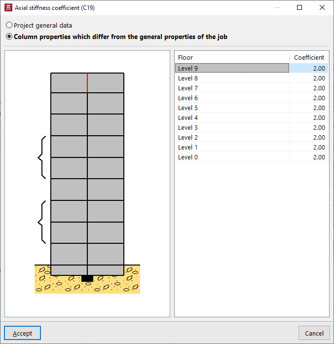
Axial stiffness coefficient
The "Axial stiffness coefficient" can be defined in the "Project general data" (from "Project" > "General data" > "By position" > "Options for columns, shear walls, walls and corbels" > "Forces"), with a default value of 2.
You can also select the "Column properties which differ from the general properties of the job" option to modify it floor by floor.
Increasing the value of the axial stiffness coefficient reduces the shortening of the columns in the analysis.
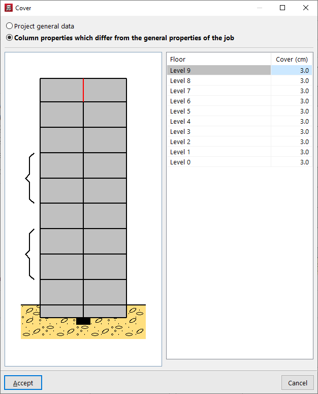
Cover
You can edit the "Cover" of the column so that it takes the value defined in the "General project data" ("Project" > "General data" > "By position" > "Common options for bars" > "Covers") or indicate "Column properties which differ from the general properties of the job". In this way, the cover value is entered for each floor.
The cover is defined as the distance from the outer face of the column to the nearest face of the stirrup bar.
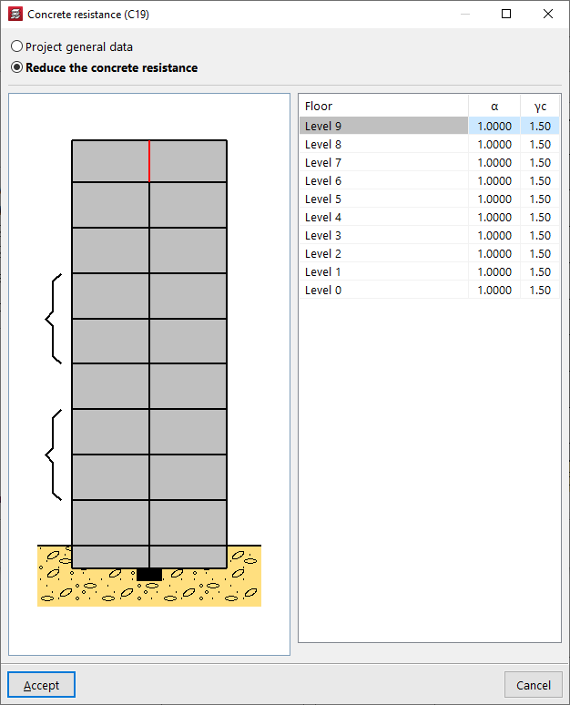
Concrete resistance
The "Concrete resistance" can be taken from the values defined in the "Project general data" or, if "Reduce the concrete resistance" is indicated, it is defined by the following parameters on each floor:
- the concrete resistance reduction factor (α);
- and the concrete strength reduction factor (γc).
Earthquake-resistant category
If seismic analysis is enabled for the project ("Project" > "General data" > "With seismic action"), it is also possible to change the "Earthquake-resistant category" for each section of the column to "Primary", "Secondary" or "Wall edge reinforcement".

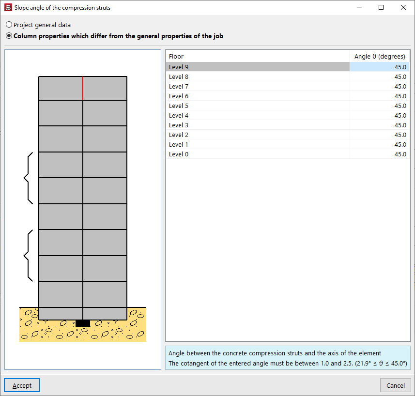
Slope angle of the compression struts
The slope angle θ of the concrete compression struts with respect to the axis of the element can be defined in the "Project general data" or modified for each column section from floor to floor if "Column characteristics which differ from general properties of the job" is selected. The cotangent of this angle must be between 0.5 and 2.
| Note: |
|---|
| All the values that define the column can be obtained from another column in the project by clicking on the "Copy from" option and then selecting a column that has already been entered and has all the information defined. |
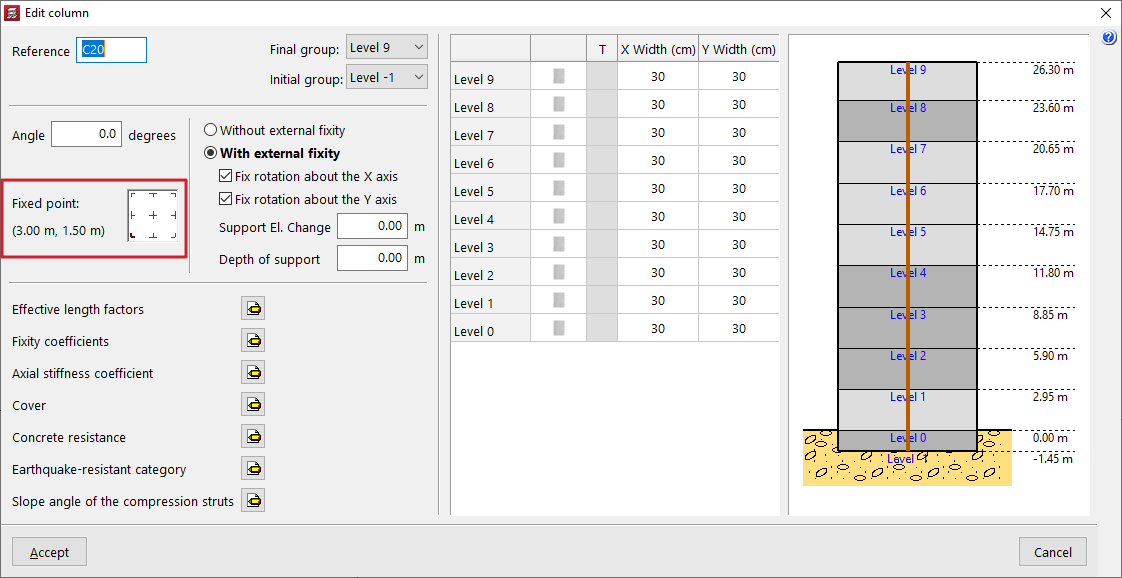
Layout of the column on the floor plan and definition of the fixed point
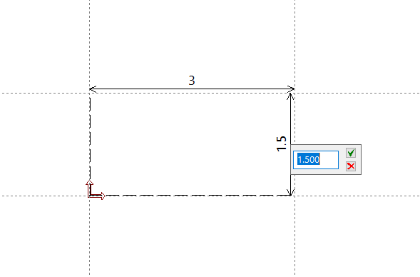
After accepting the characteristics definition window, the column is inserted into the floor plan. If you click anywhere in the space, its position is indicated by entering the X and Y coordinates relative to the reference point.
To position the column, you can also use the "Template snaps" and/or "Layout lines" previously entered in the model.
The position of the pointer when clicking while capturing a point influences the definition of the fixed point of the column, or point common to all floors from which the growth of the column section is determined. This fixed point can be centred in the column section or located at the edges or corners of the column.
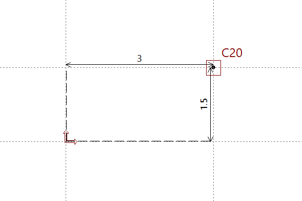
At any time, using the "Edit" option in the "Insertion" > "Column, shear walls and starts" menu, you can consult the definition of the"Fixed point" of the column entered and modify it if necessary. You can also change the other parameters used in the column definition.