Force distribution in shear walls and walls
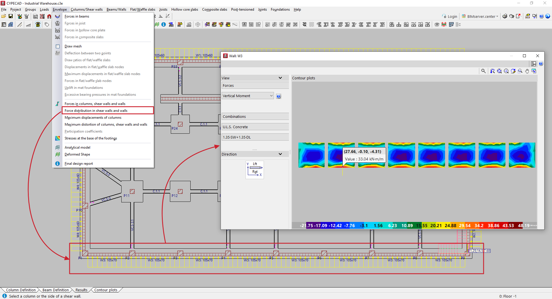
To view the force distribution in slabs and walls in CYPECAD, once the structure has been analysed, open the "Results" tab and navigate to a group where the wall you wish to view is visible. Then, open the "Envelopes" menu at the top of the interface.
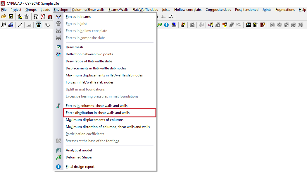
Force distribution in shear walls and walls
By selecting the "Force distribution in shear walls and walls" option and clicking on a wall section or a segment of a shear wall, you can view the results for that section in a pop-up window.
In the results viewer, the "View" section in the top-left corner is used to select the display type, whether it be "Discretisation", "Displacements", "Forces", "Stresses" or "Main stresses". Each of these options is explained below.
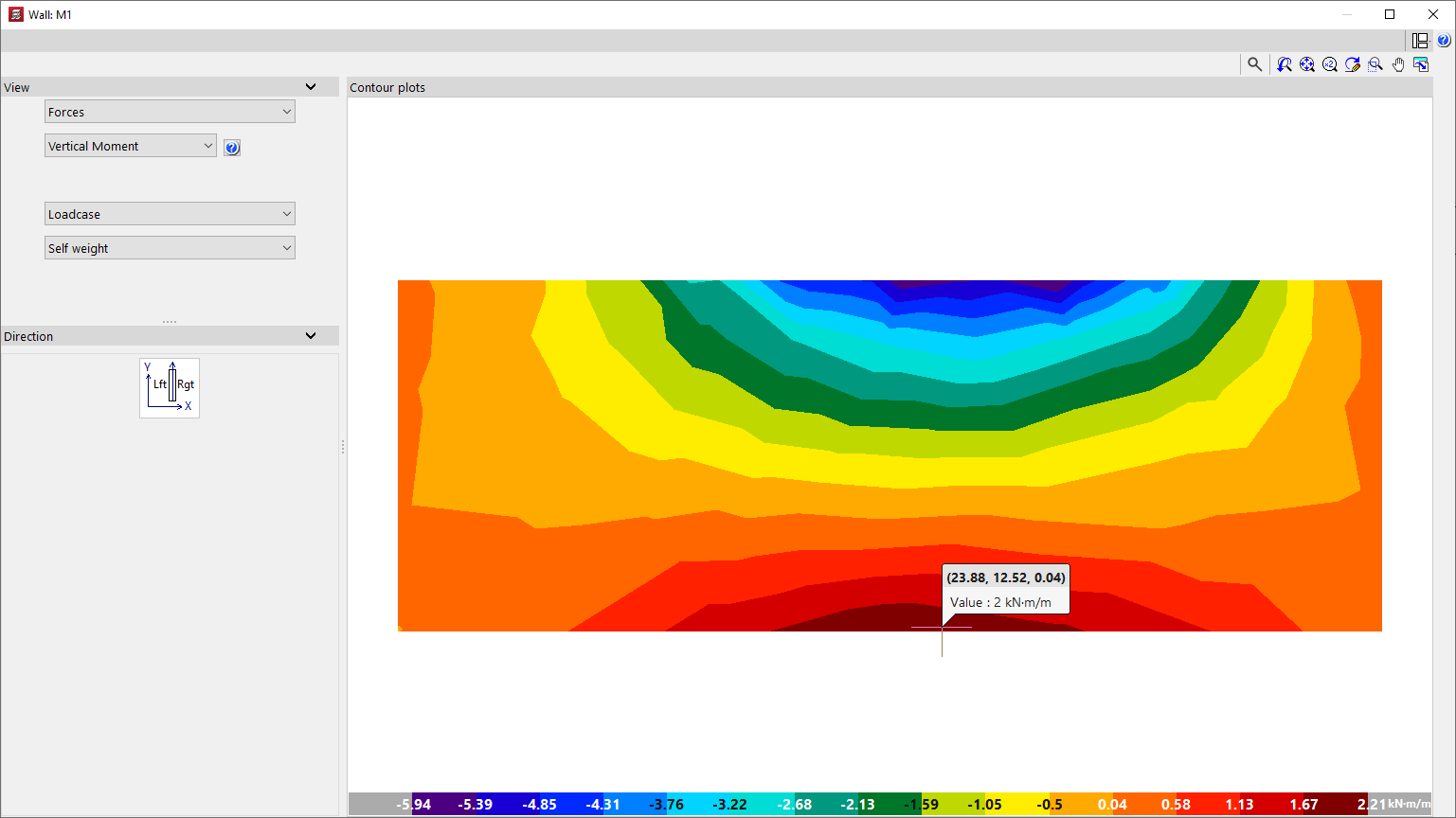
Forces
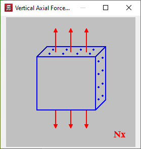
If "Forces" is selected as the display type, the program displays the following stresses for viewing:
- Vertical axis
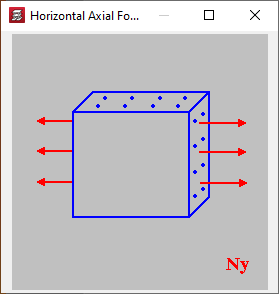
- Horizontal axis
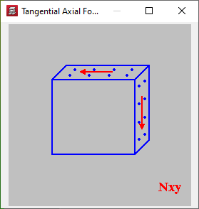
- Tangential axis
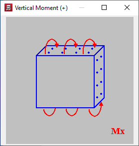
- Vertical moment
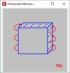
- Horizontal moment
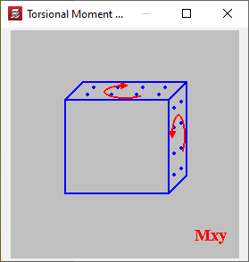
- Torsional moment
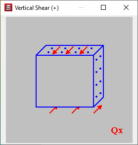
- Vertical shear force
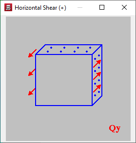
- Horizontal shear force
Clicking on the accessible help button on the right brings up an explanation of the selected effort level and the criteria for the positive sign.
In the diagram below, the section "Direction" shows the position of the shear wall or wall on the floor plan in relation to the building’s main axes, as well as the direction of its left and right sides.
The overview on the left shows an elevation diagram of the shear wall or wall, with the different values of the selected forces represented by a colour gradient.
The units of the gradients and the minimum and maximum values for each step of this gradient are shown on the colour scale at the bottom of the display.
Displacements
Selecting the "Displacements" option displays the displacement and rotation diagrams for all points on the screen or wall relative to the three general axes of the structure, as well as the "Total Displacement":
- X displacement
- Y displacement
- Z displacement
- X rotation
- Y rotation
- Z rotation
- Total displacement
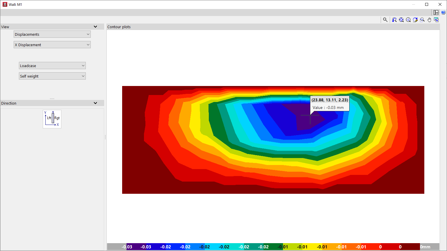
In both the "Displacements" and "Forces" windows, the program allows you to select the loadcase, combination or envelope you wish to view:
- Loadcase
The calculated values for the selected simple loadcase will be displayed. - Combinations
The calculated values for the specified combination of loadcases will be displayed once you have selected one of the available combination groups. - Envelopes
The "Maximum" or "Minimum" forces envelope for all loadcase combinations in the selected combination group will be displayed.
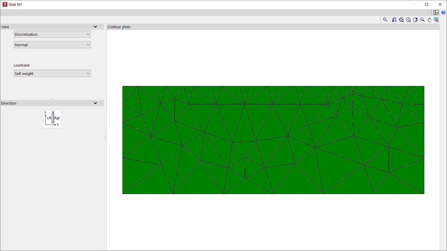
Discretisation
When you select "Discretisation", the layout and geometry of the triangular finite elements generated during the analysis of the shear wall or wall are displayed.
The discretisation can be displayed in the following ways, which can be selected from the relevant drop-down menu:
- The "Normal" option allows you to display the connection nodes between the finite elements;
- the "Reduced" option hides these link nodes;
- Finally, the "By floors" option allows you to colour the finite elements by storey.
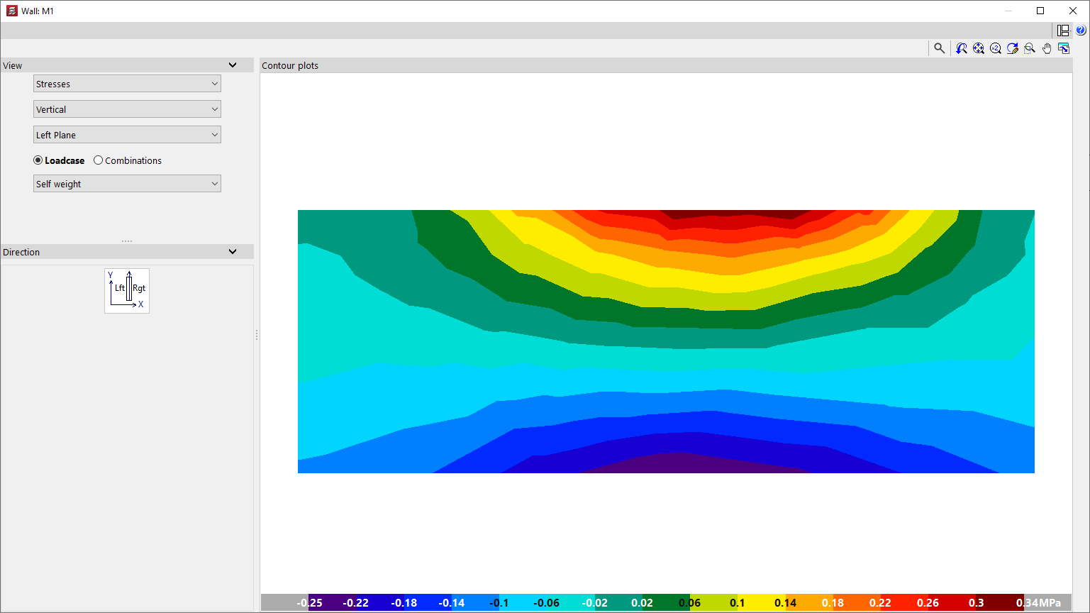
Stresses
You can view the following "Stresses" on the screen or display by selecting the relevant option:
- Vertical
- Horizontal
- Tangential in the Plane
- Tangential Vertical
- Tangential Horizontal
The voltages can be viewed on the "Right-hand panel", the "Central panel" or the "Left-hand panel" of the screen or wall.
Finally, you select a simple "Loadcase" or one of the calculated "Combinations" of loadcases.
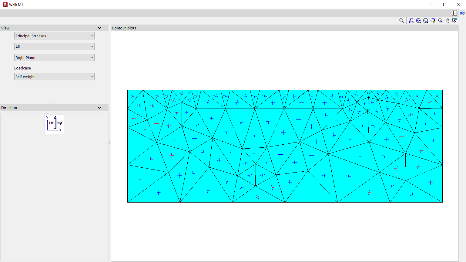
Main stresses
Selecting "Main stresses" displays a representation of these stresses on each plane of the screen or wall, for the selected simple "Loadcase".
You can display "All" stresses, or only "Tension" or "Compression" stresses, for each of the finite elements that make up the screen or wall.
In addition, the stresses can be displayed on the "Right-hand plane" or the "Left-hand plane" of the screen or wall.