Inserting strap and tie beams
Strap and tie beams can be entered via the “Beam input” and “Results” tabs. This option will be available when you are in a group where a column or screen defined as “With external connection” begins, or a wall with a continuous footing or “Fixity” at its base. To move to the desired group, use the “Move up group”, “Go to group” and “Move down group” options.
To insert a strap or tie beam, open the “Foundations” menu at the top and select the “Strap and tie beams” option.
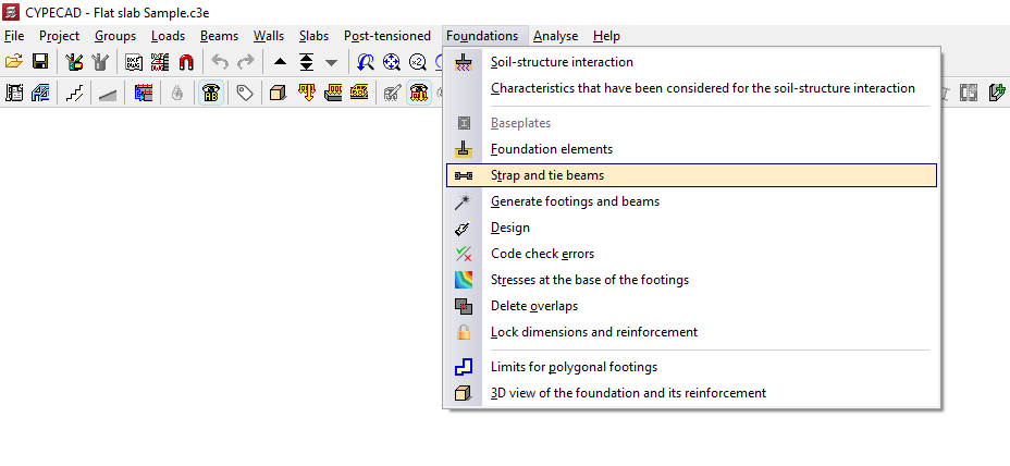
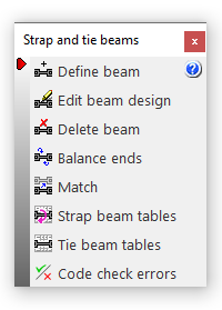
This opens the "Strap and tie beams" window, which displays the following options:
- Define beam
- Edit beam design
- Delete beam
- Balance ends
- Match
- Strap beam tables
- Tie beams tables
- Code check errors
Beam selection
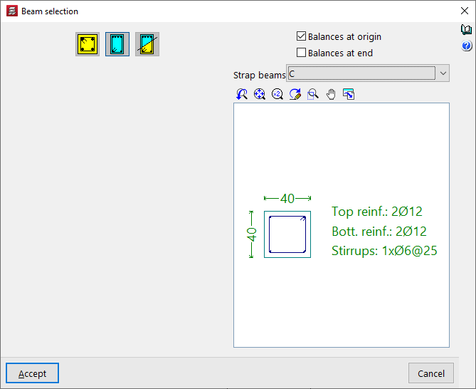
The "Enter beam" option allows you to enter strap or tie beams.
To do this, in the "Beam selection" window that appears, you must first select one of the following options: "Tie beam", "Strap beam" or "Beam with automatic centring at the ends":
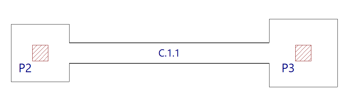
Tie beams
If you select the "Tie beam" option, you can choose the type of tie beam from the drop-down menu at the top.
The central display shows the dimensions and the longitudinal and transverse reinforcement associated with the selected beam type.
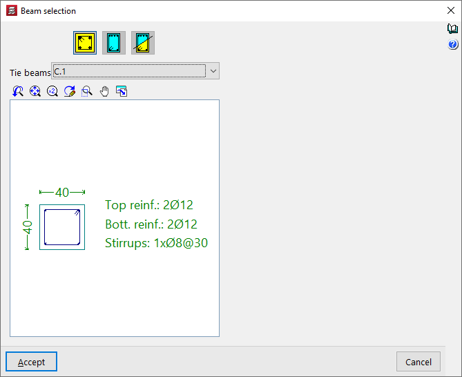
After clicking "Accept", the beam is inserted into the floor plan by left-clicking to select its start and end points, using, if necessary, the snap points on the beam heads and foundation elements such as footings and/or pile caps that have been drawn previously.
Strap beams
If the "Strap beam" option is selected, you must specify whether the beam "Balances at origin" or "Balances at end" by checking the relevant boxes. At least one of the two checkboxes must be checked. If you do not wish to balance either end, a tie beam will be used.
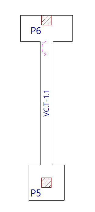
Next, as in the previous case, select the type of strap beam from the drop-down menu and, after clicking "Accept", draw the beam on the plan view using the left mouse button.
The start and end points of a centring beam depend entirely on the order in which the data is entered. Once entered, circular arrows appear at its junctions with footings or abutments. These arrows indicate that, at the end where they appear, the beam is centring the load from the footing or abutment along the longitudinal axis of the centring beam.
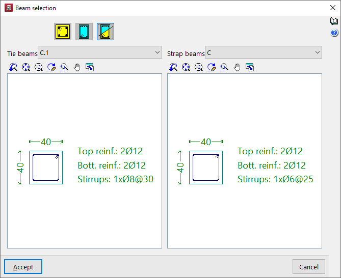
Beam with automatic centring at the ends
The "Beam with automatic centring at the ends" option allows the program to automatically identify the need for load centring at the ends when drawing beams in contact with corner or party wall footings.
To do this, after clicking on the option, you must specify the two possible beam types in the "Reference" drop-down menus, whether the beam is a tie beam or a strap beam.
After clicking "Accept", use the left mouse button to place the beam on the floor plan in the same way as in the previous cases.
This time, the program will automatically use a tie beam if it is placed between two centrally positioned footings, and strap beam if one of the beam’s ends is in contact with a corner or party wall footing, applying and displaying load centring at the end where necessary.