Modifying reinforcement for slabs and waffle slabs
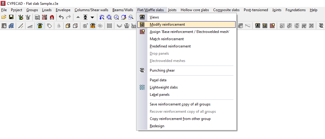
The "Modify reinforcement" option, available in the "Slabs/Waffle slabs" menu on the "Results" tab, allows you to make changes to the reinforcement obtained from the analysis of slabs and waffle slabs.
After clicking on this option, the "Modify reinforcement" window opens. Here, first select the type of reinforcement you wish to modify, either "Longitudinal" or "Transverse", and then "Top" or "Bottom".
The "Keep reinforcement views" option allows you to display the reinforcement sets activated via "Slabs/Waffle slabs > Views", which will appear alongside the reinforcement set selected for modification. This allows you, for example, to view the lower longitudinal reinforcement whilst modifying (and therefore also displaying) the upper longitudinal reinforcement.
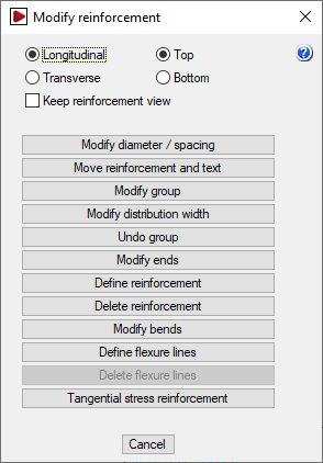
The "Modify reinforcement" window then offers the following options, which will be applied to the reinforcement type selected in that window:
Changing diameters and/or spacing
The "Modify diameters/spacing" option allows you to change the diameters of the bars in a reinforcement bundle and, in the case of slabs, the spacing between bars.
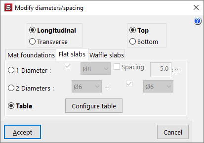
Clicking on this option opens the "Modify diameters/spacing" window.
First, select the reinforcement to be modified: "Longitudinal" or "Transverse", and "Top" or "Bottom". Next, select the appropriate tab based on the type of floor slab being used: "Mat foundation", "Flat slabs", or "Waffle slabs". Once these selections have been made, there are three ways to modify the reinforcement.
- 1 Diameter
The "1 Diameter" option allows you to modify the representative bar for each reinforcement bundle. If you are modifying a slab, the parameters that can be modified are the diameter and/or the "Spacing". If you are modifying a grid, the modifiable parameters are the diameter and/or the number of bars (“No. of bars”). Once the parameters have been selected, click “OK” and then left-click on the bar in the bundle to be modified. - 2 Diameters
The "2 Diameters" option allows you to define two bars in a reinforcement package, so that it consists of pairs of bars in different layers which may have different diameters. If you are modifying a slab, enter the diameters of each of the bars. In grid slabs, you can also define a specific number of bars for the first diameter and another for the second diameter. Once the parameters have been selected, click "OK" and then left-click on the pair of bars in the package to be modified. - Table
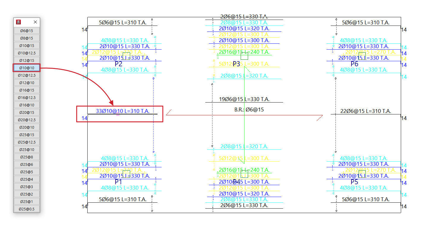
When you select the "Table" option and click "OK", the reinforcement table for the relevant floor slab type will appear on the left-hand side of the screen. The reinforcement is sorted from smallest to largest cross-section. By clicking on one of the reinforcement sets in the table and then clicking on the reinforcement sets or bundles of reinforcement on the floor plan with the left mouse button, the reinforcement set selected in the table is assigned to them. To cancel the operation, click the right mouse button.- The grid that appears can be customised by clicking on the "Configure grid" option. Here you can specify the "Number of rows" and the "Number of columns". By default, a single column and 50 rows are set.
Move layout and text
This "Move reinforcement and text" option allows you to move the reinforcement bar drawings and tags for grouped reinforcements to a different position within the reinforcement package, as specified by the user.
After selecting this option, select the reinforcement to be moved and then the final position where you want to place it.
Modify group
The "Modify group" option allows you to change both the diameter and the length of a group of bars or ribs in grid slabs and slabs simultaneously. In the case of slabs, it also allows you to change the spacing between bars.
When you select an assembly, the "Modify group" window opens, displaying the parameters to be modified, such as the diameter of the package’s bars, their spacing, the bar length, and the tab length. You can tick the relevant boxes to add a second or even a third bar to the package on different layers.
At the bottom of this window, a diagram of the selected assembly is displayed, which changes as the data in the upper section is modified. After clicking "OK", the program updates the assemblies in the package.
Modify distribution width
A distribution band is the area in which a specific set of evenly spaced reinforcements is arranged. Using the "Modify distribution width" option, you can extend or reduce a distribution band by selecting one of its edges (the band’s outline is highlighted in red when selected) and moving it to a new position.
When modifying the distribution band of a reinforcement, it may overlap with other reinforcements. If the "Delete overlapped reinforcement" option is enabled, any reinforcements that overlap by at least half their length will be removed, whilst the reinforcements in the modified package will be retained.
Undo group
The "Undo group" option allows you to break down the selected assembly into individual bars, so that they are no longer grouped together.
Modify ends
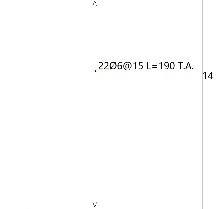
Using the "Modify ends" option, you can extend or shorten the ends of a selected bar. To do this, click on the end of a bar (the length to be extended or shortened is shown in yellow or blue, respectively) and then click again on the new position for that end.
Define reinforcement
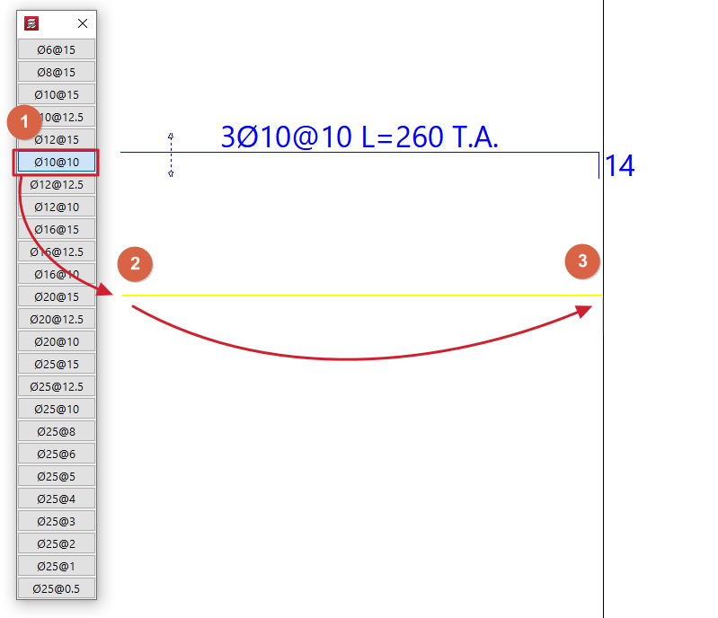
The "Define reinforcement" option is used to add new bars with the diameter and/or spacing selected in the table that appears.
After selecting the diameter and/or spacing from the table, use the cursor to mark the two ends of the bars.
Delete reinforcement
The "Delete reinforcement" option allows you to remove the selected reinforcement package.
Modify bends
The "Modify bends" option allows you to adjust the lengths of the pins.
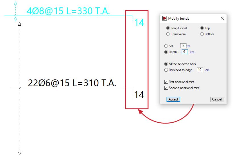
Clicking on this option opens the "Modify bends" window. Here, you must first select the position of the reinforcement to be modified: "Longitudinal" or "Transverse", and "Top" or "Bottom".
You can then specify a fixed dimension or define the cantilever based on the edge of the slab:
- Fixed
Allows you to specify the bend length directly. - Overhang - 'X'
You can enter a value of 'X'. The cantilever will have a length equal to the overhang of the slab minus the value 'X' entered.
Further down, you can choose whether to modify all the selected bars or only those near the edges:
- All selected bars
If this option is selected, all bars selected subsequently will have a stirrup attached, even if they do not reach the edge of the slab or openings. - Close to the edge: 'X'
If this option is selected, the specified bracket will be applied to all beams selected subsequently whose ends are less than 'X' centimetres from the edge of the slab.
The following options are also available:
- First reinforcement (optional)
If you enable this option, the specified connection will be applied to all first reinforcement bars (the longest bar if there are several) selected below. - Second reinforcement (optional)
If you enable this option, the specified tab will be added to all the second reinforcement bars (the shortest bar if there are several) that you select below.
After clicking "Accept", select the bars to be modified in the workspace.
| Note: |
|---|
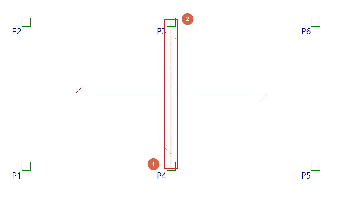
| Bars can be selected by clicking directly on them with the cursor or by using a selection area or window. To do this, click the first point of the window and then a second point: -If you drag from left to right, a solid line window will appear and all bars that are completely within the window will be selected. -If you drag from right to left, a dashed line selection window will appear and the bars within the window will be selected, even if only partially. |
Define flexure lines
The "Define flexure lines" option allows you to enter bending lines using two end points. These can be entered in line with the directions of the supports. The distance between the lines corresponds to the span length.
| Nota: |
|---|
| These lines are treated as if they were points of maximum negative moment. Based on these, and following the minimum percentage distances between lines specified in "Project > General data > By position > Options for slabs, grids and unidirectional elements > Minimum lengths for grids and slabs", the lengths of the negative reinforcement are calculated. Furthermore, the positive reinforcement bars are overlapped on these lines, where possible. It is advisable to make this input before the calculation, as if done afterwards, the overlaps will be construction-related (30 centimetres) and will not be recalculated. |
Delete flexure lines
The "Delete flexure lines" option allows you to remove previously entered fold lines.
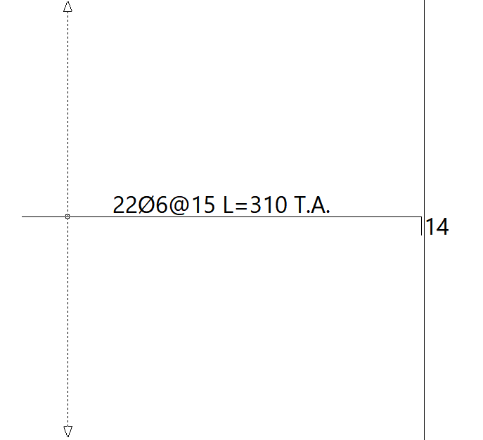
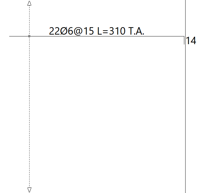
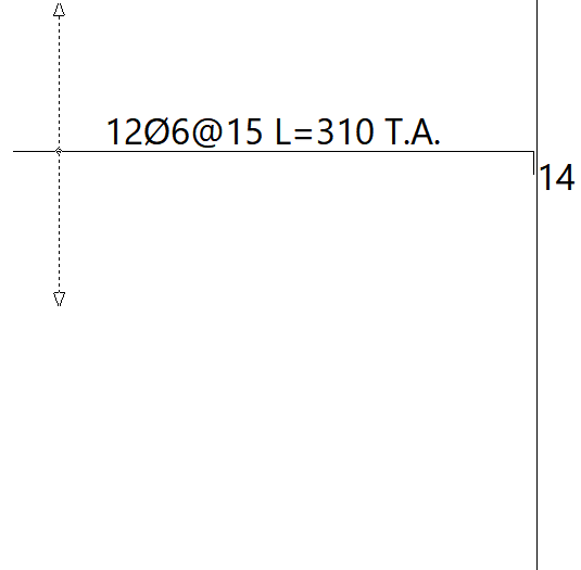
Tangential stress reinforcement
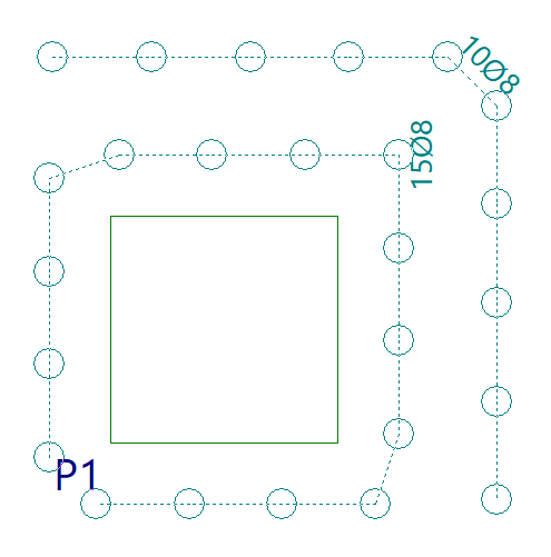
The "Tangential stress reinforcement" option allows you to modify the reinforcement for tangential stresses, whether for individual bars or groups of bars.
A group of bars refers to several consecutive bars of the same diameter, shown connected by a dotted line.
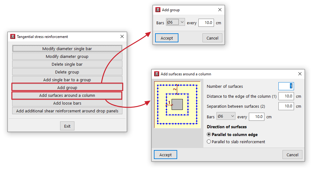
Clicking on this option opens the "Tangential stress reinforcement" window, which contains the following options:
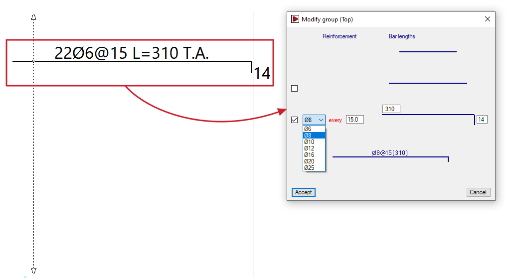
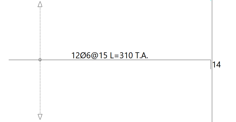
- Modify diameter single bar
Allows you to specify a new diameter for a bar. To do this, select the bar on the plan view. If the bar belongs to a group, it will be ungrouped. - Modify diameter group
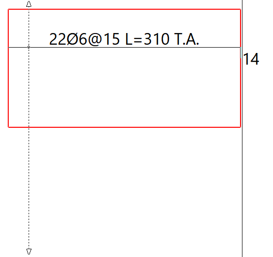
Allows you to specify a new diameter for a group. To do this, select the group of bars on the floor plan. - Delete single bar
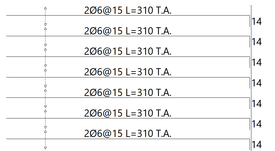
Allows you to delete a single bar or a bar belonging to a group. - Delete group
Allows you to delete an entire group of bars. - Add single bar to a group
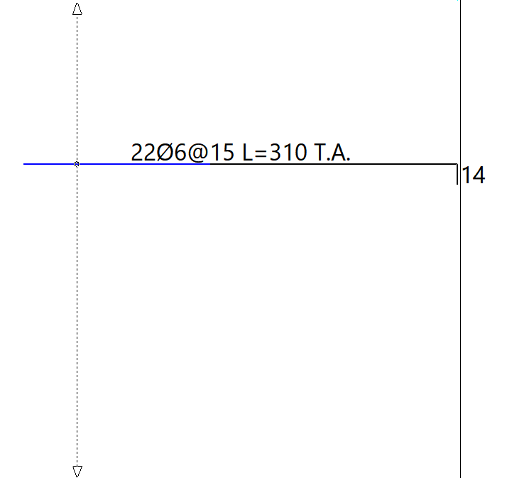
This allows you to insert a single bar into a group of bars. You can only add single bars to groups from which bars have previously been deleted. - Add group
Enter the diameter and spacing of the bars in the group. You must then specify the start and end points of the group on the screen. - Add surfaces around a column
This allows you to generate reinforcement for shear stresses on surfaces around a column. To do this, define the "Number of surfaces", the "Distance to the edge of the column" for the first surface, the "Spacing between surfaces", the diameter of the "Bars" and their spacing. You must also select the "Direction of the surfaces", either "In the direction of the column" or "In the direction of the panel". After clicking "OK", select a column in the plan view. The program will generate the groups of bars around it according to the defined settings. - Add loose bars
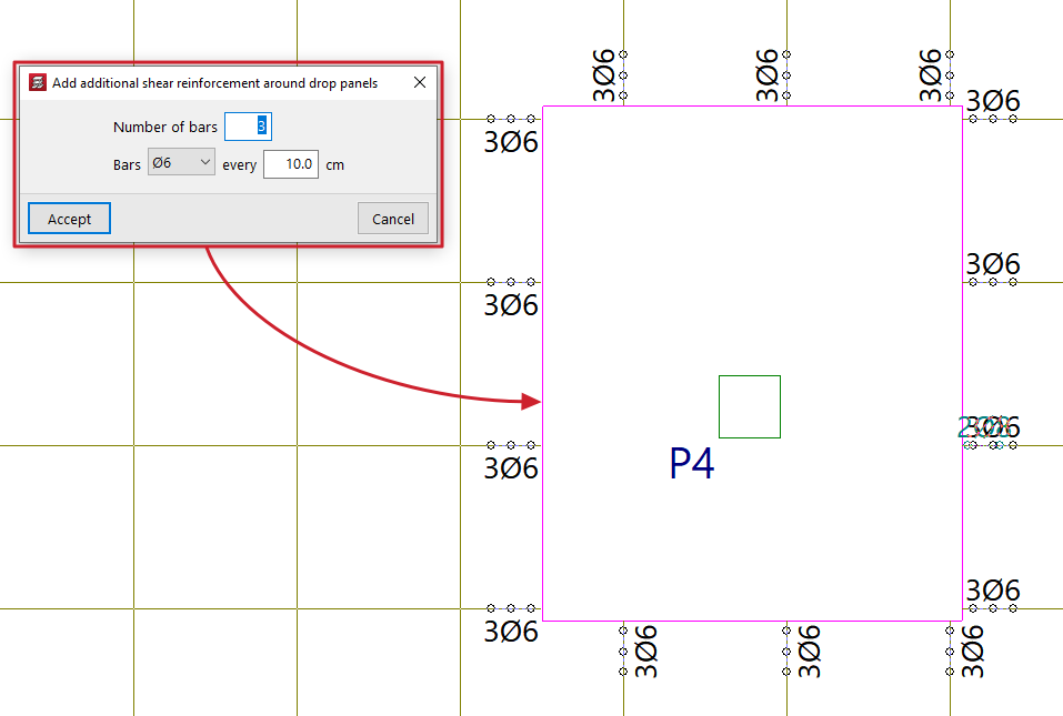
Allows you to insert a loose bar. - Add additional shear reinforcement around drop panels
This allows you to add groups of shear reinforcement bars to all ribs connected to a slab without having to select each rib individually. To do this, specify the "Number of bars" to be placed, their diameter and spacing, and select the slab on the floor plan. The new bars will be added even if shear reinforcement bars already exist in the ribs connected to the selected abacus. If you wish to replace the existing bars with different ones, you must first delete the existing reinforcement and then add the new bars.