Panel manager options
The "Panel manager" option, available within the "Slabs" menu on the "Beam input" tab, provides access to a menu containing various options relating to the input, viewing and modification of the structure’s floor slabs.
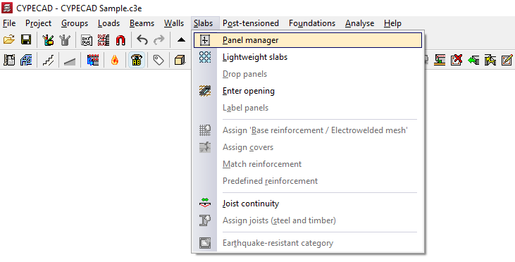
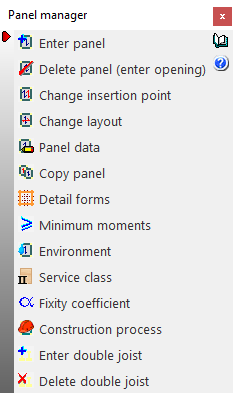
The available options are as follows:
- Enter panel
- Delete panel (enter opening)
- Change insertion point
- Change layout
- Panel data
- Copy panels
- Detail forms
- Minimum moments
- Environment
- Service class
- Fixity coefficient
- Construction process
- Enter double joist
- Delete double joist
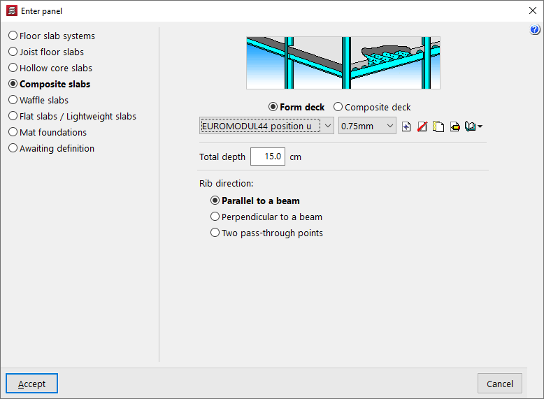
Enter panel
This allows you to select a floor slab type (in the "Enter panel" window that appears) and then insert a slab of the selected type into a closed perimeter on the floor plan, previously defined by beams and/or walls.
The following types of floor slabs are available:
- Floor slab systems
- Joist floor slabs
- Hollow core slabs
- Composite slabs
- Waffle floors
- Flat slabs / Lightweight slabs
- Mat foundations
- Awaiting definition
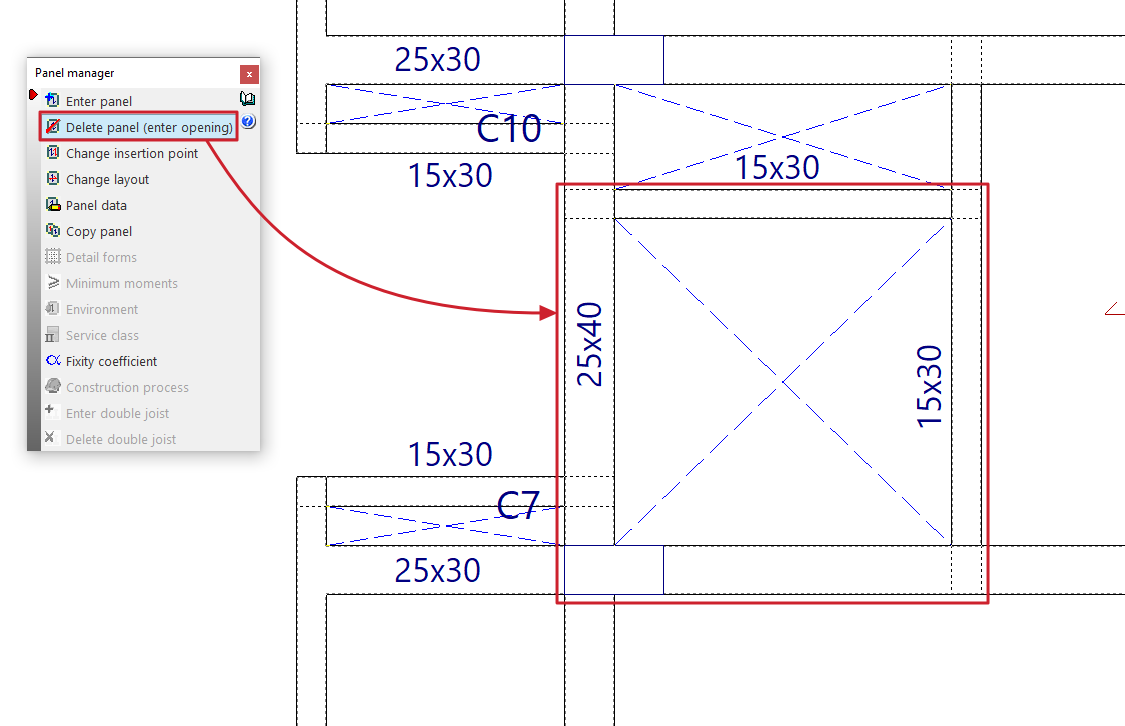
Delete panel (enter opening)
This allows you to remove a floor slab and insert an opening within a closed perimeter on the floor plan, previously defined by beams and/or walls.
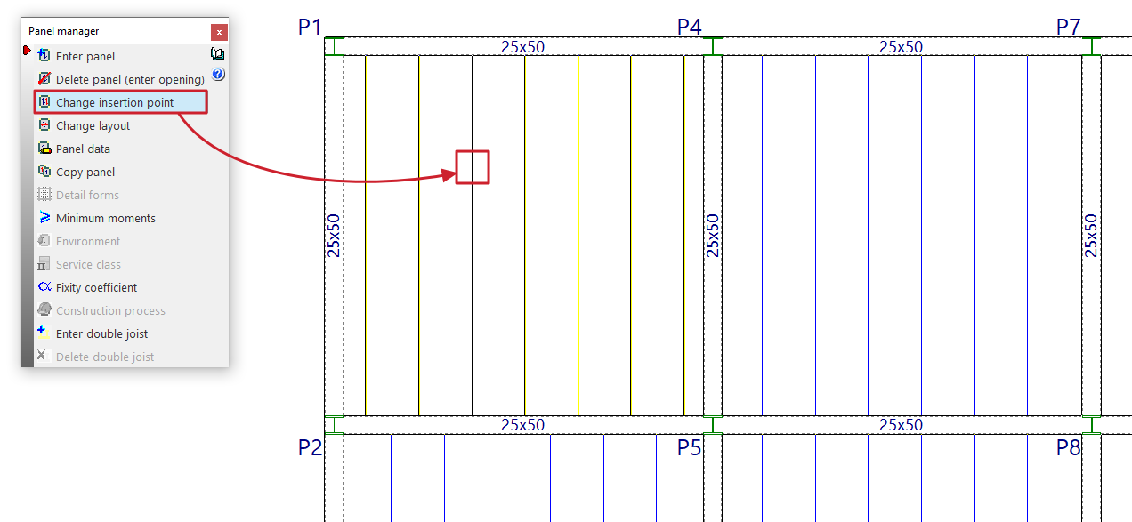
Change insertion point
This option allows you to change the insertion point of the joist, rib or reinforcement of the selected panel.
To do this, after selecting the option, you must select the panel. Then, click on the new point through which you want the joist, rib or reinforcement of the panel to be inserted.
This procedure can be useful for re-routing the ribs if there are small openings in the floor slab; in this way, the opening can be aligned with the hollow blocks or lightweight sections.
| Note: |
|---|
| Joists in adjacent sections may be misaligned by up to 20 centimetres whilst maintaining continuity with one another. |
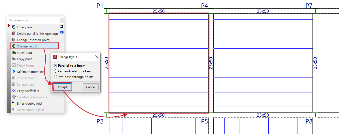
Change layout
This option allows you to change the direction of the joists, beams or reinforcement bars in a panel.
To do this, you must first specify whether the direction to be defined is "Parallel to a beam", "Perpendicular to a beam" or defined by "Two points of intersection".
Next, select the panel with the mouse and then specify the new direction of the joists, beams or reinforcement by selecting a beam or the two required connection points.
When changing the layout of a panel, the reference point marked when the slab was installed remains in place.
Panel data
When this option is selected, the mesh number for each panel is displayed on the plan view (the drop panels, ribs or openings in each panel generate meshes with their corresponding numbers).
Next, when you left-click on a panel added to the floor plan, a dialogue box displaying its properties will appear.
For example, the data that the program displays for a joist floor is as follows:
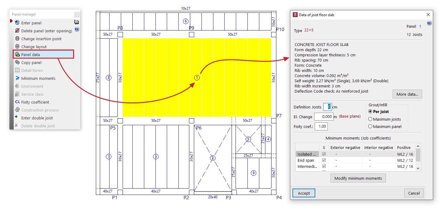
- First, the "Type" of the floor structure, the number of "Sections" and the number of "Joists" are displayed.
- The main technical specifications of the selected floor slab are then listed; the full description can be viewed by clicking the "More data" options.
- You can change the length of the joist section that is inserted into the beam by entering the value in "Enter joists". This is used solely for the purposes of measuring and drawing the floor structure on the plan.
- In "Slope", you can apply a positive or negative horizontal slope value to the panel relative to the elevation of the current floor plan's base plane. This option is equivalent to the one available under "Groups > Sloped slabs / Elevation changes". Furthermore, the elevation changes entered for each slab will appear in the list of slabs with elevation changes managed via this latter option.
- It is also possible to modify the fixed support coefficient ("Fixed support coefficient") for the ribs around the entire perimeter of the panel. A value of 0 corresponds to hinged elements, whilst a value of 1 indicates a fixed support. Intermediate values are permitted to simulate partial fixed supports.
- Where compression reinforcement is required in the area where the top reinforcement is located, the forms shall be removed until they are no longer necessary. This shall be indicated on the floor plan by a solid line representing the joists, shown in blue. The options in the "Infill" section allow you to configure the removal of forms or lightweight elements:
- if "Per joist" is selected, the required solid section is applied to each joist;
- if "Maximum joists" is selected, the joist requiring the most reinforcement is identified, and this is applied to all adjacent joists;
- if "Maximum panel" is selected, the joist requiring the maximum solid section is chosen and applied to the entire panel;
- Finally, the "Minimum moments" assigned to the panel via the corresponding option in the "Panel manager" menu are displayed. You can also modify these directly for the selected panel by clicking on the "Modify minimum moments" option.
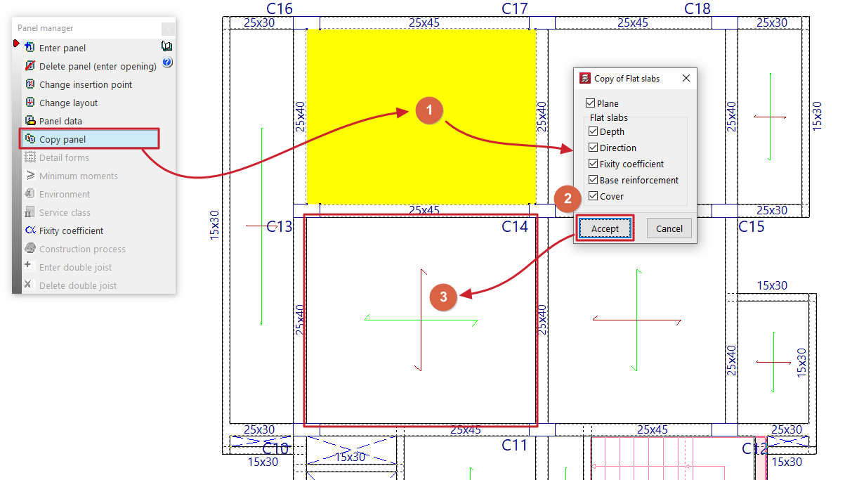
Copy panels
This option allows you to copy data from one panel to another.
First, left-click on the panel from which you wish to extract the information. The program will then display a dialogue box where you can select the data to be copied by ticking or unticking the relevant boxes.
Once you have accepted, use the left mouse button to select the panels to which the data will be copied, either by selecting them one by one or by dragging to select an area.
If you wish to change the source panel, simply right-click and repeat the previous steps.
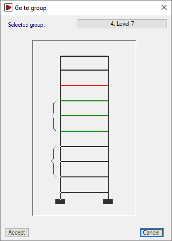
Copy panel from one group to another
It is also possible to copy data from a panel in one group to another panel belonging to a different group of floors.
To do this, after clicking the "Copy panels" option, right-click and select the group containing the source panel from the “Go to group” window.
Once you have selected the sheet and confirmed the dialogue box specifying the data to be copied, the program will return to the group of floors that was visible when the option was selected.
| Note: |
|---|
| Copying panels also ensures that the joists and ribs of the panels are aligned and that there is continuity in the assembly. It is therefore advisable to insert one panel and copy the rest, as inserting them all manually may result in a slight difference in the alignment of the ribs (greater than 20 cm), which could prevent continuity in the floor slab. Furthermore, in the case of a cantilevered joist floor, the load-bearing element is the joist, so the joists from the panel adjacent to the cantilever must be copied. |
Detail forms
This option will be available once at least one waffle slab panel has been defined on the floor.
When you click on this option, the actual layout of the ribs in the waffle slabs and the details of the forms will be displayed.
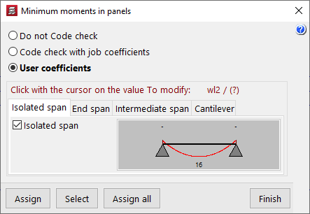
Minimum moments
This option allows you to modify and assign the minimum positive and/or negative moments to be withstood by joist floors, lightweight slabs and composite slabs; it will be available if there is at least one section of these types on the floor.
In the window that appears when you click on "Minimum moments", the program allows you to select one of the following options:
- Do not Code check
The program will not perform the minimum moment check on the marked floor slabs. - Code check with job coefficients
The program will use the minimum moments defined under "Structure > Slab options > Minimum moments to cover with slab reinforcement". - User coefficients
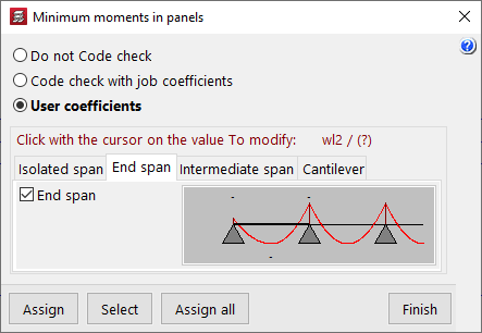
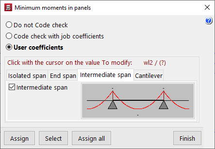
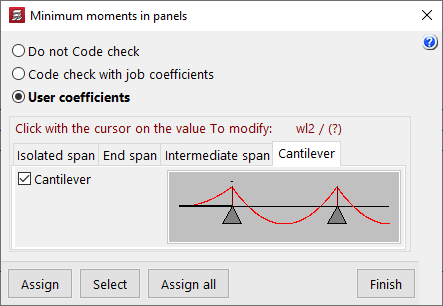
Allows you to modify the coefficients that define the minimum moments according to the type of span. To modify these coefficients, left-click on the value to be modified in each of the diagrams that appear when selecting the different tabs (“Isolated span”, “End span”, “Intermediate span” and “Cantilever”). The coefficient is equivalent to the denominator 'A' in the expression p*L²/A, where 'L' is the span length and 'p' is the load.
| Note: |
|---|
| By default, the program assigns minimum positive moments of pL²/16 to isolated and intermediate spans and pL²/12 to end spans. |
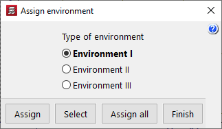
Environment
This option will be available once at least one panel of hollow core slabs has been defined on the floor plan.
When you click on the option, you can select the type of environment to apply ("Environment I", "Environment II" or "Environment III").
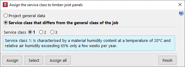
Service class
This allows you to select and assign a specific service class to timber joist floors.
This may be the one defined under "General project data" (within the "Project" menu) or a "Service class that differs from the general class of the job", in which case the specific class must be selected.
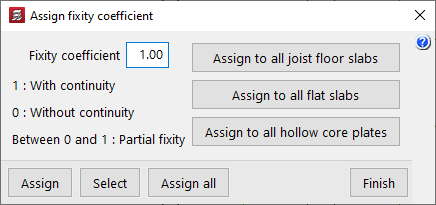
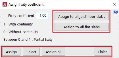
Fixity coefficient
This allows you to define an "Fixity coefficient" between 0 and 1 and assign it to a floor slab consisting of joists, flat slabs or hollow core slabs. This coefficient defines the degree of fixity of the joists, panels or slab edges into the faces of all the perimeter beams that form the perimeter of the slab.
A value of 0 indicates that the joists, slabs or slab edges are hinged (they are not connected to the beam), whilst a value of 1 indicates that they are rigidly connected to the beam (there is a continuous connection with the beams). Intermediate values are permitted to define partial fixed connections.
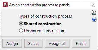
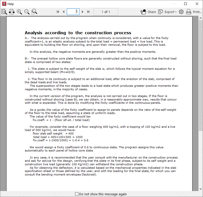
Construction process
This option will be available once at least one panel system has been defined on the floor plan, and allows you to assign the "Construction process" to it for analysis purposes. This can be:
- Shored construction
In this case, a fixity coefficient of 1 is assumed at the edges of the slab, which allows the simulation of a construction of these slabs using support beams. With this option, the negative moments are usually greater than the positive moments. - Unsupported construction
In this case, a fixity coefficient equal to 1 – (Self-weight of the floor slab / Total load [including the self-weight of the floor slab, live load and dead loads]) is assumed. This allows for the two-stage analysis required when constructing this type of floor slab without beams. With this option, the positive moments are usually greater than the negative moments.
The button on the right provides access to detailed information about the analysis performed based on the selected construction process.
Options for assigning data to floor slabs
When using several of the above options ("Minimum moments", "Environment", "Service class", "Fixity coefficient" and "Construction process"), the program offers the following options for assigning the data to the panels:
- Assign
Allows you to select the panel to which you wish to apply the selected condition. - Select
Allows you to extract information from a selected panel on the floor plan. - Assign all
Applies the selected condition to all panels in the current group. - Assign to all joist floor slabs / Assign to all flat slabs / Apply to all hollow core slabs / Apply to all composite slabs
These tools appear only in some of the options mentioned and allow you to apply the selected condition to all floor structures of the specified type present on the floor. - Finish
Closes the options window.
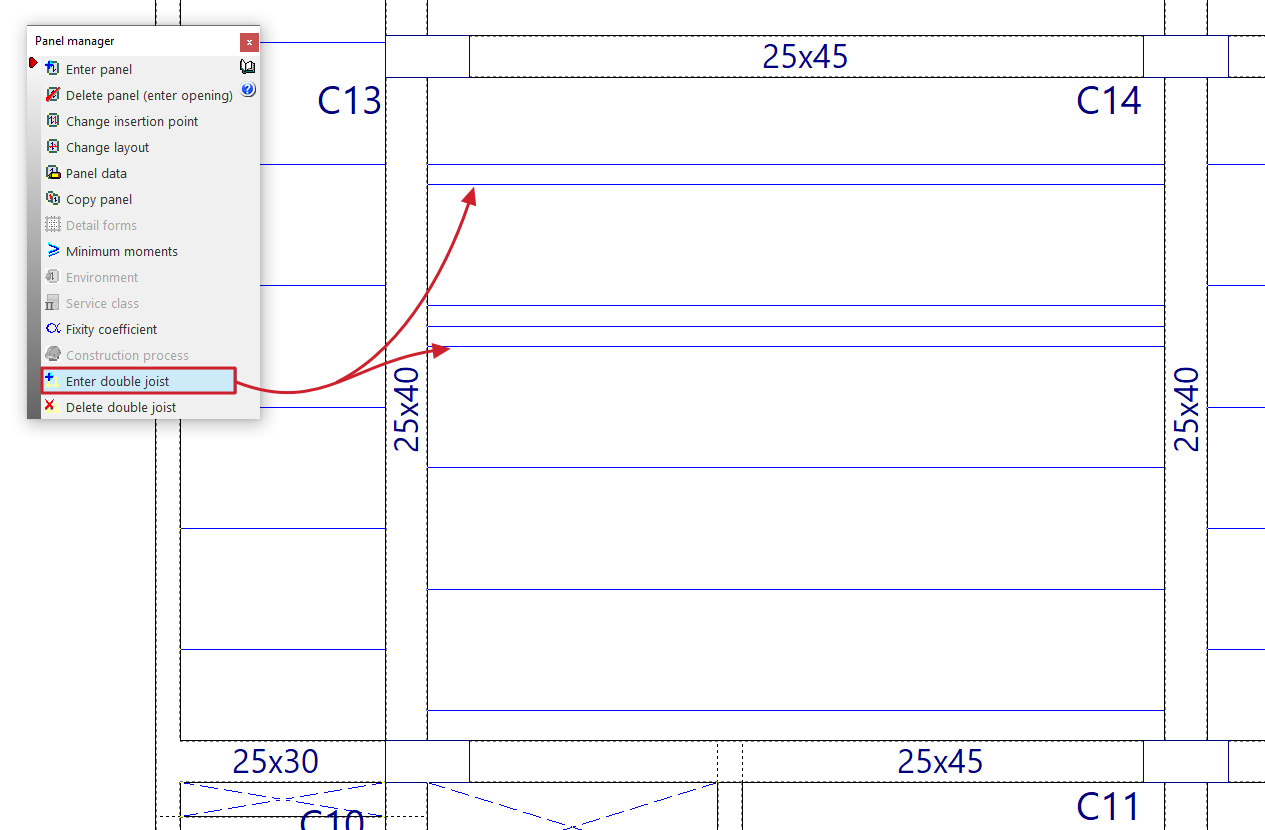
Enter double joist
This option allows you to define double and/or triple joists, and will be available once at least one joist floor slab or floor slab system has been defined on the floor.
To do this, tap to the right or left of one of the joists in a floor slab. Doing so will insert a double joist (if a single joist is selected) or a triple joist (if a double joist is selected) at the selected position.
Delete double joist
This option allows you to remove double and/or triple joists defined in joist floors or in floor slab systems entered on the floor plan.
To do this, left-click on the double or triple joist you wish to remove.