Reports
Drawings
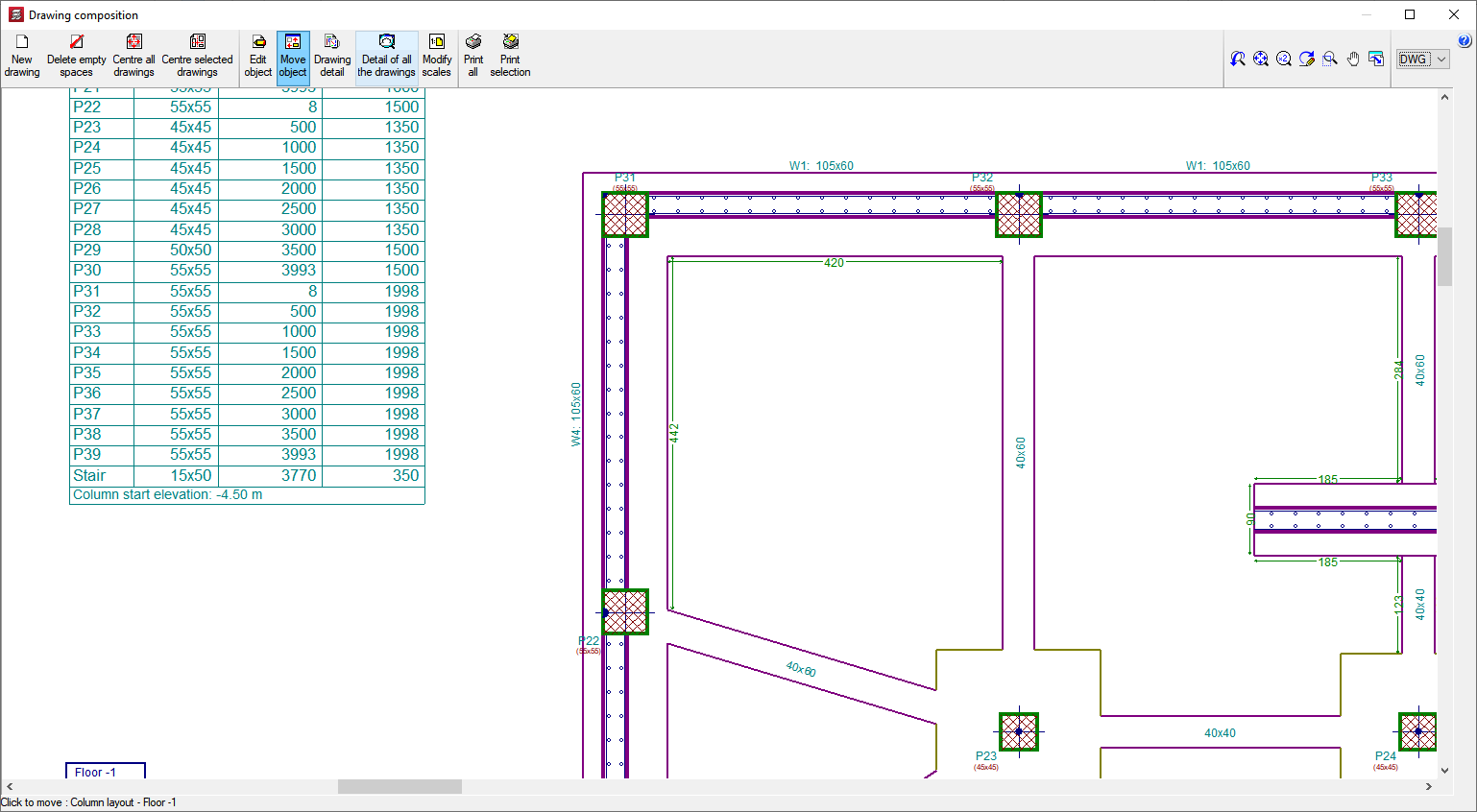
Project plans can be configured in different paper formats and sizes, either standard or user-defined. Furthermore, they can also be drawn by printer, plotter or exported to DXF and DWG format. In the floor drawings, the DXF or DWG files that have been used to define the job can be included. They can be integrated entirely or only the desired layers, such as stairs, for example.
A drawing editor is available on the job's own floors, which provides users with a wide range of resources: adding dimensions, texts, sections of the building, construction details in DXF format, floor slab sections, modifying the location of texts, etc. These modifications are saved with the project.
CYPECAD has an extensive library of steel, concrete, composite and inclined slab construction details available to be incorporated into any of the drawings generated by the program.
You can apply any scale, line thickness, font size, title block, etc. This way, the drawing of the plan can be completely customised.
CYPECAD provides complete and clear drawings. You can obtain drawings of the layout, floor plan, foundations, beams, column schedule, detailing of columns and shear walls, foundation loads, wall elevations, stair detailing, loads, corbels, etc. They optionally include measurement tables and reinforcement details. These can be configured so that each user can obtain the drawings according to their needs. CYPECAD has an editor that allows text to be moved while viewing the drawings on screen.
Reports
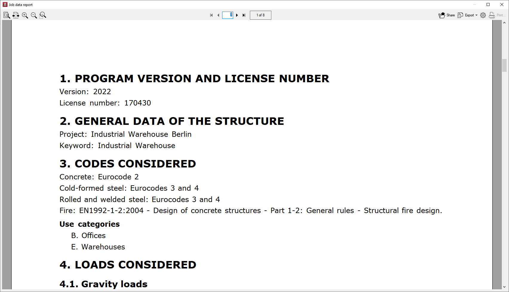
Users can easily obtain reports of all the data entered and the results: list of project data, combinations used in the analysis, foundations, corbels, envelopes, reinforcement and quantities of all the elements, job ratios, horizontal wind loads, participation coefficients (seismic loads), second order effects, etc.
All this can be obtained either on screen or by printer, but files can also be created in HTML, DXF, DWG, RTF, PDF formats, etc.
The reports that are generated include the following:
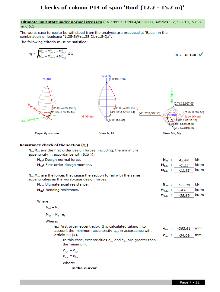
Detailed ultimate limit state check reports
CYPECAD, CYPE 3D and the Portal frame generator generate detailed ultimate limit state (U.L.S.) check reports. The U.L.S. reports contain all the checks these programs carry out to design concrete, steel, aluminium and timber elements. Each check refers to the design code and article requiring the check, or the criteria which have been applied to carry it out. The detailed contents of the U.L.S. reports make these essential documents with which users can verify, justify and optimise the design of the structural elements that have been analysed.
The level of detail of these reports also acts as a guide allowing users to know all the checks to which the structural element is submitted.
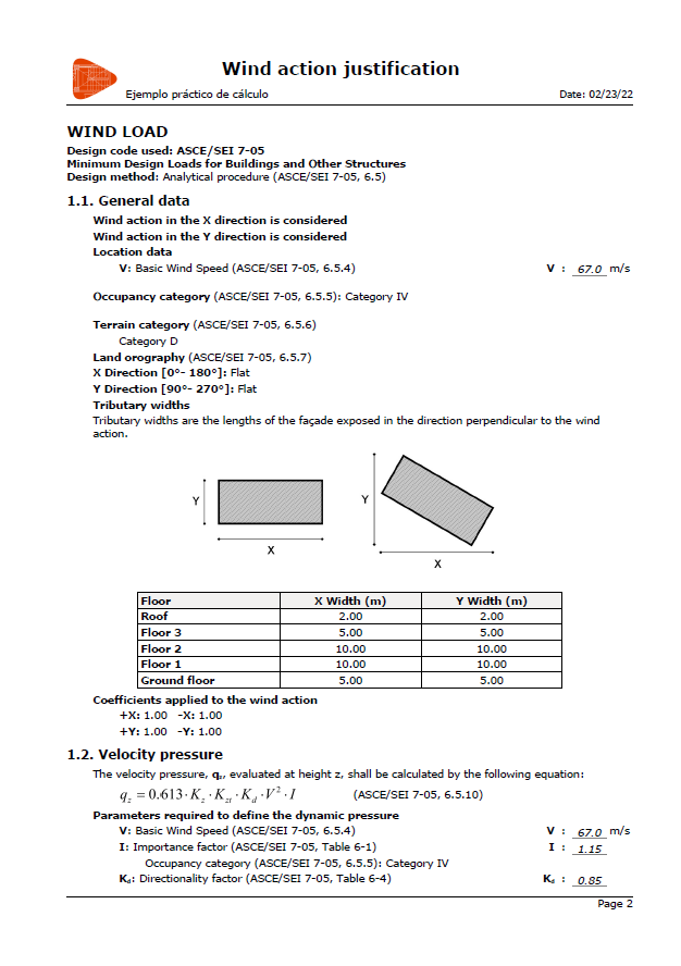
Wind action justification report
CYPECAD also generates wind action justification reports. By selecting the image below, a PDF showing an example of this report can be downloaded.