
Analysing, checking and designing
Within the "Installation" tab, in the "Analysis" group of the main toolbar, there are options for analysing, checking and designing the elements in the model:

The program uses the EPANET 2 analysis engine (developed by the Water Supply and Water Resources Division of the National Risk Management Research Laboratory) to perform the hydraulic analyses required for the design of sprinkler and fire hydrant networks. The use of EPANET allows an accurate analysis result to be obtained, valid for compliance with any of the codes available in the program or the configuration that is entered manually.
Update results
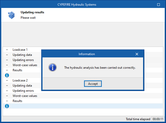
This will analyse the entered system according to the latest changes, including all design scenarios, update the calculated parameters in the elements and check if they are within the permitted ranges.
The result is a direct display with error or warning messages about the parts of the system that have a problem or fail a check, as well as the results and reports available after the analysis in the "Checks" section of the editing panel of the elements that have this feature.
Design
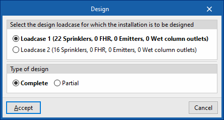
Designs the network according to the indicated loadcase, automatically selecting the size of the pipes.
The "Design" panel has two options:
- Select the analysis scenario for which you want to design the system
Select one of the defined analysis scenario in order to carry out the design. The number of sprinklers, fire hose reels, emitters and wet riser outlets assigned to the scenario is shown in brackets. - Type of design
- Total
The entire job is designed. - Partial
Only the design of the part of the system downstream of a given control point is carried out. To do this, after accepting the panel, a "Control point" previously entered in the installation must be selected.
- Total
In the editing panel of some elements such as tanks, the program can also be used to design the element with the corresponding tool in the lower right-hand area.
| Note: |
|---|
| The analysis and design of an automatic sprinkler system can be quite complex. All the hydraulic analysis requirements that comply with the different applicable standards make the selection of the size of the pipes to be used one of the most complex tasks in the system design. The design tool can be configured from "Design criteria" under "Code configuration". From this panel it is possible to edit the pipe diameters to be used in the design and the maximum number of sprinklers that each diameter can feed until jumping to the next diameter. The "Design" tool will launch the diameter selection process and then the hydraulic analysis. This selection and hydraulic analysis process will be finished if no errors are found when comparing the results obtained with the requirements defined in the project options. Otherwise, the process shall be repeated until valid diameters are selected to comply with the selected standard or the defined configuration. |

Consult checks
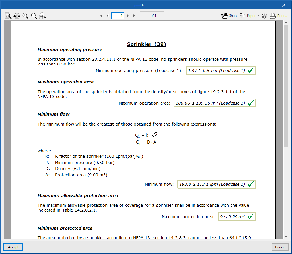
Consults the checks carried out in the last analysis performed on the job. After selecting the option, users can click on the elements in the system to directly access the list of checks carried out on the same.
If any changes have been made to the elements in the system, the "Update results" option must be used so that the program will update the results displayed.
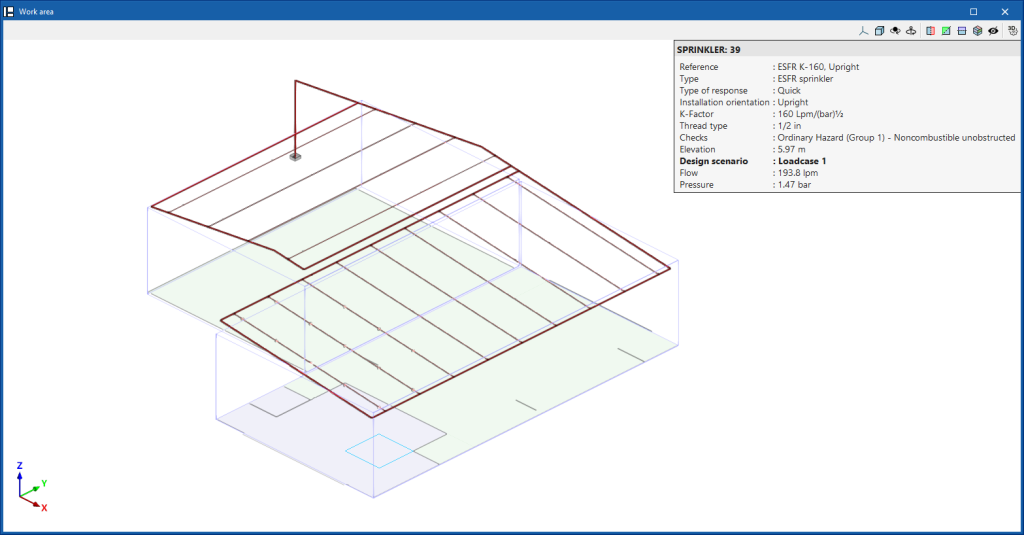
Show/Hide results
If this option is activated, the elements in which an error has occurred are highlighted. By hovering the cursor over these elements, the message describing the error can be displayed.
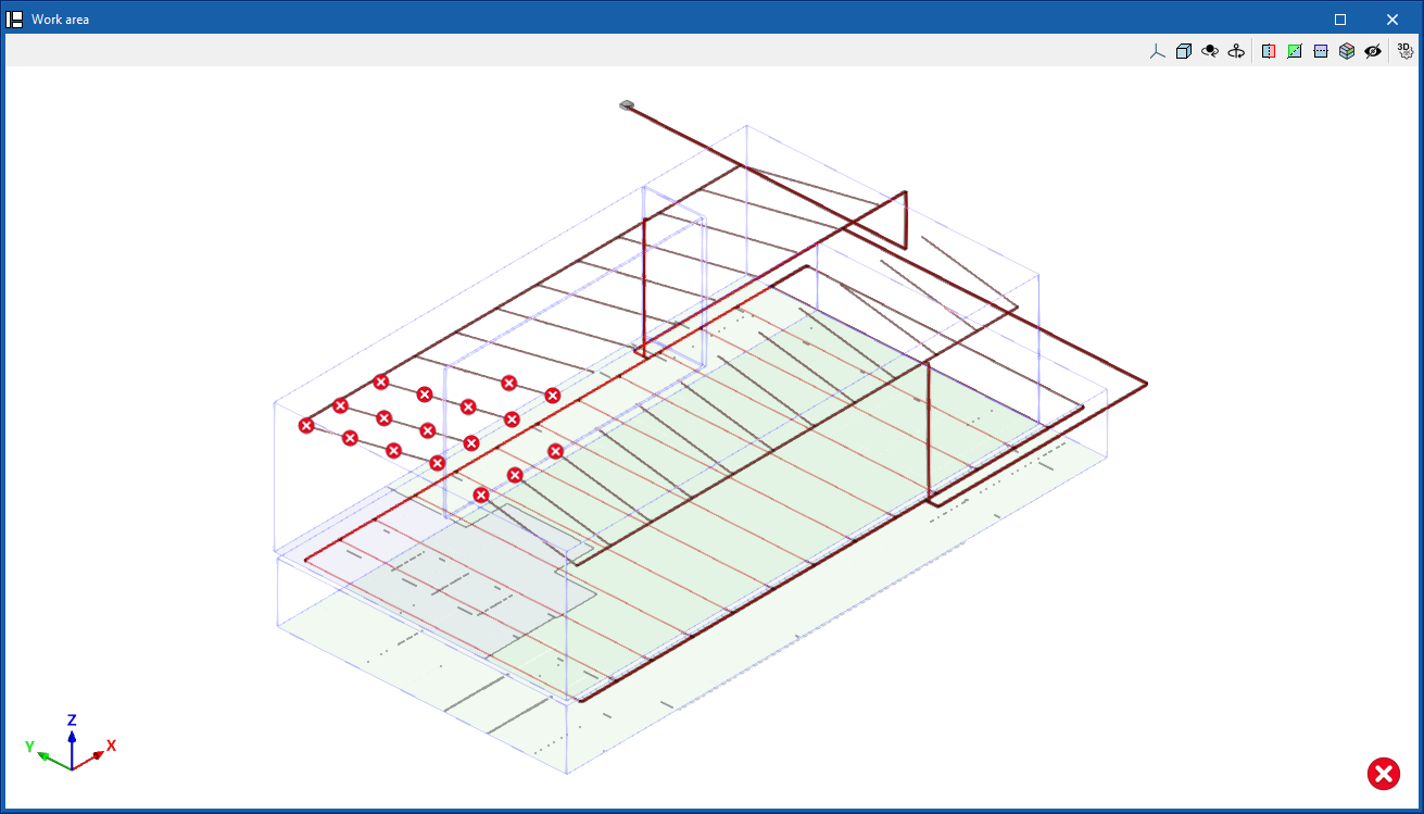
Collision analysis
During the design process, after performing the hydraulic analysis, the program analyses the geometry of the system's elements and architectural model elements, such as beams and columns, and performs a collision analysis between them. In this way, it can show errors with the location of the points in the model where these problems occur to help the user with the system layout.