Initial generation and collector generation
Within the "Installation" tab, in the "Generation" section of the main toolbar, you will find the option to perform the initial generation of installation elements, as well as options to generate manifolds up to the sprinkler networks, manually enter connection points, or force the installation’s passage points.

Example (single-storey building)
The procedure for the complete installation of a hydraulic fire-extinguishing system in a single-storey building is as follows:
- Model preparation:
- Importing spaces with the required properties for "Initial generation", either during the initial model import process or by editing "Spaces" (as "Read elements").
- Importing doors during the initial import of the model, or adding a "Horizontal pipe run" between spaces.
- Initial generation:
- Creating the deposit within the area defined as the "Deposit Area".
- Creating the pressure zone within the area defined as "Space reserved for the pump supplying the sprinkler system".
- Generation of the sprinkler network using the main options in the "Generate" group. Each sprinkler tree must have a "Connection point" with the associated "Pressure group" selected.
- Generation of manifolds between the pressure unit and the connection points on the sprinkler trees (using "Generate manifolds"). These manifolds pass through the doors or horizontal pipe runs that have been entered.
The various options mentioned are set out below:
Initial generation
This option initiates a process to generate the vertical pipe runs (used to position the risers connecting to dry and wet column systems and equipped fire hydrants), as well as the necessary pressure units and tanks.
To generate vertical runs of pipework, pressure units and tanks, the model must contain enclosures or spaces extracted from the BIM model with the following properties selected, depending on the requirements of the installation:
- Space for the tank
- Space reserved for the pump supplying the sprinkler system
- Space reserved for the pump supplying the fire hose system
- Space reserved for the pump supplying the wet riser system
- Vertical routing for sprinkler systems
- Vertical routing for FHR systems
- Vertical routing for wet standpipe systems
- Vertical routing for dry standpipe systems
These properties can be viewed or edited for spaces via "Edit > Edit".
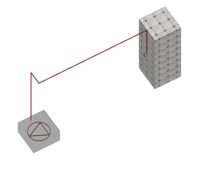
Generate collectors
This option initiates a process to generate the collectors required for:
- Connecting the tank to the booster set
- Connecting the booster set to the designated connection points on the sprinkler systems, fire hose reels and wet risers
- Connecting the dry risers
A single booster set can be used to supply the various categories of components or the different networks, or several booster sets can be used, depending on the project design. To do this, each connection point on the sprinkler networks, each fire hose reel and/or each wet riser must be associated with the desired booster set in its editing panel.
The program will use the doors in the BIM model to establish the horizontal pipe penetration points from one room to another. If the model does not contain these elements, you can enter the horizontal pipe penetration points manually at their correct positions using the "Horizontal pipe penetration" option.
For the vertical route, it will use the vertical pipe penetrations entered manually via the "Vertical pipe penetration" option or generated via "Initial generation".
| Note: |
|---|
| Currently, the height of the pipes generated using this option is fixed and cannot be edited during the generation process. However, the user can modify the geometry afterwards using the standard element editing tools. |
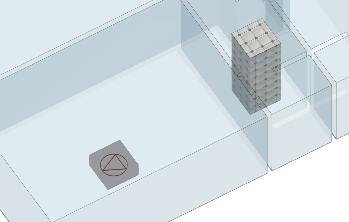
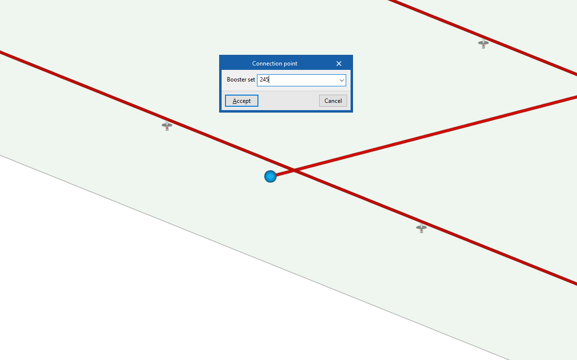
Connection point
This option allows you to manually enter a connection point located on a sprinkler network. Connection points are reference points used during the manifold generation process to define the connection between the booster sets and the sprinkler system.
When entering the connection point, select the "Booster set" to which it is associated in the pop-up window.
A connection point must be provided at the start of each independent sprinkler system or tree. The software will draw manifolds from the pump station to each connection point when you use the "Generate collectors" option.
| Note: |
|---|
| Connection points do not need to be installed on the fire hose reels or wet risers, as the equipment itself acts as a connection point. |
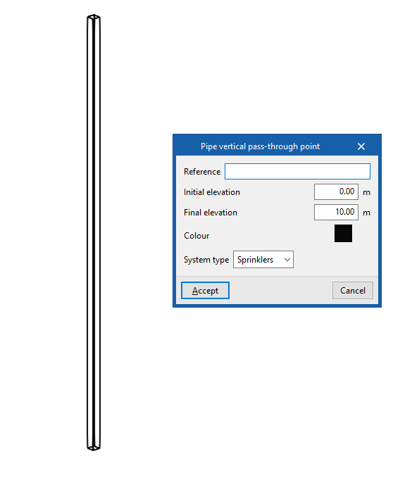
Pipe vertical pass-through point
This allows you to manually enter the vertical offset of the pipes generated using the "Generate collectors" option.
The installation of a vertical pipe run can be supplemented by the installation of several horizontal runs at the points where pipes enter and exit the vertical run on each floor.
When entering a vertical pipe run, the following details must be provided:
- Reference
Step reference. - Final elevation
Final elevation of the vertical pipe run in absolute coordinates. - Colour
Display colour. - System type
Select the type of system served by the vertical passage:- Sprinklers
- Fire hose reels
- Dry riser
- Wet riser
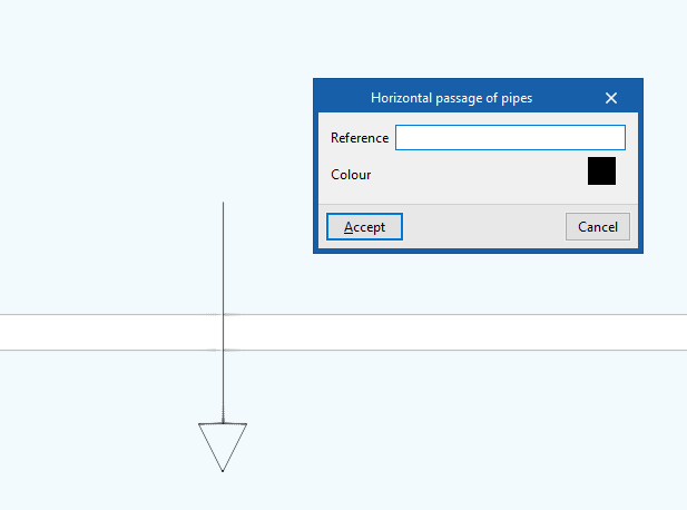
Horizontal pipe run
This allows you to specify or force the position of the horizontal pipe run generated using the "Generate collectors" option. This element can be positioned between two spaces or between a vertical pipe run and a space.
If there are horizontal passages, the program will attempt to use their position to generate the pipe layout, routing the pipes through them rather than using the position of the doors.
When entering a horizontal passage of pipes, the following details must be provided:
- Reference
Passage reference. - Colour
Display colour.