Work environment
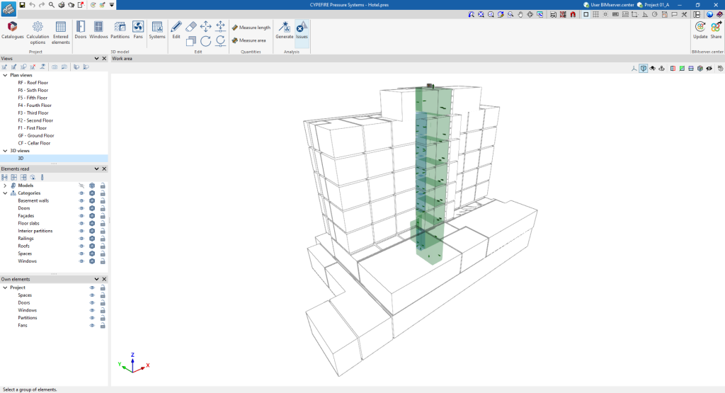
The CYPEFIRE Pressure Systems interface has a similar work environment to other CYPE tools and features a system of dockable windows that can be customised to adapt the workspace to the project's needs.
This environment allows the system's design to be carried out quickly and easily, both in a 3D view and in any type of 2D view (such as floor plans and elevations). This way, the elements in the system can be entered using the most appropriate view at any given time.
The tab shows the following:
- An upper toolbar containing the tools for: managing the general characteristics of the project; entering the air leaks and the elements of the installation; defining and generating the pressure differential systems; using the editing and measuring tools; and checking the installation.
- The modelling area, on the right-hand side of the screen, where all the elements of the project are entered, edited and displayed.
- On the left-hand side, there are several panels with tools to define the views of the project and to manage the visibility of the elements read and the own elements.


