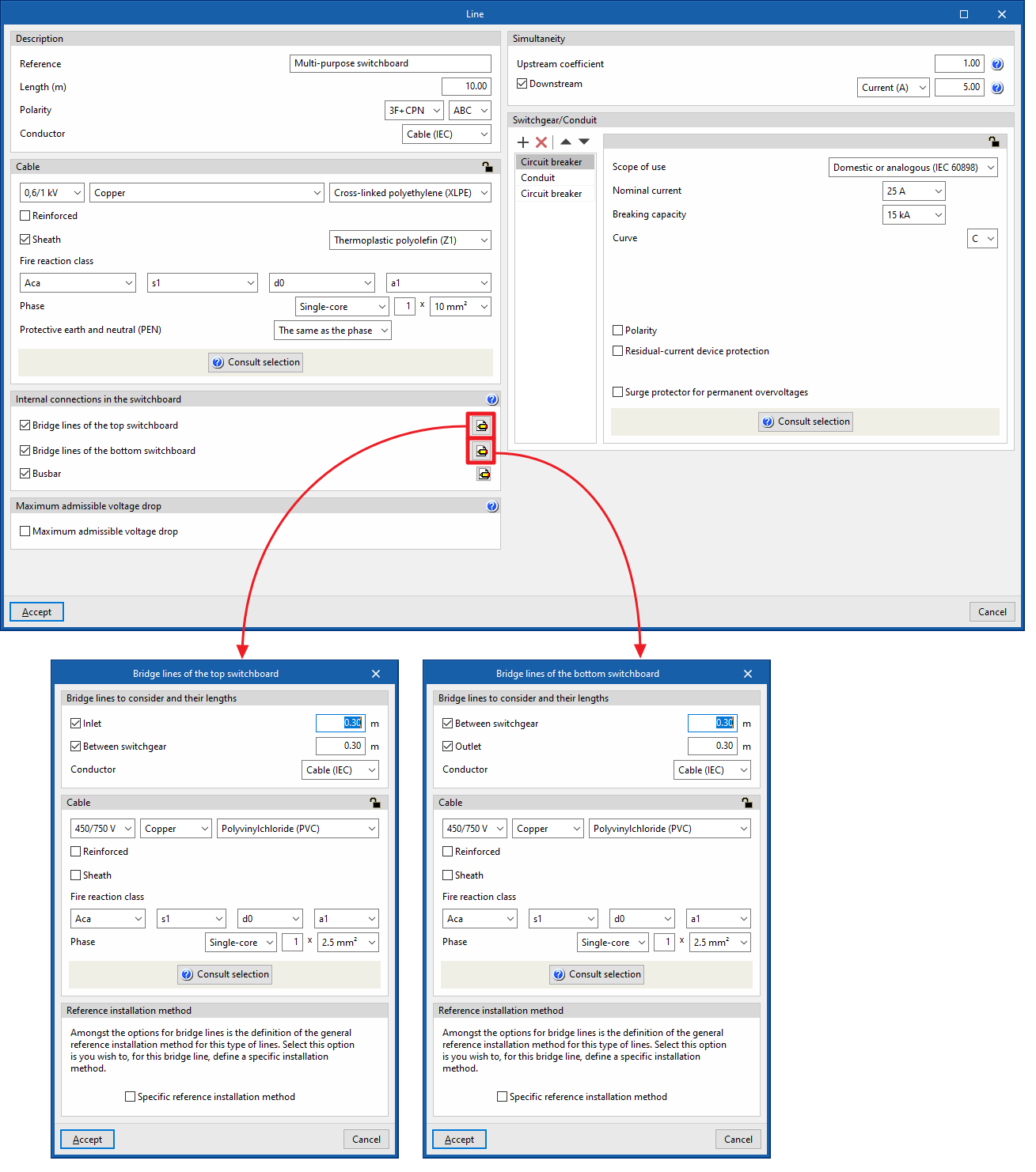
Defining bridge lines
In high-power installations, users must correctly design the internal connections in the control and protection panel (busbars and bridge lines).
All switchgear elements that are located between the raceways of two consecutive levels shall be included in the same switchboard.
Bridge lines are the lines used to connect devices located in the same switchboard.
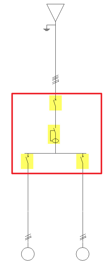
Two groups of bridge lines will be distinguished according to their location in the conduit: bridge lines at the top (which establish an interconnection between the elements located upstream of the conduit) and bridge lines at the bottom (which connect the devices located downstream of the conduit).
Bridge lines of the top switchboard
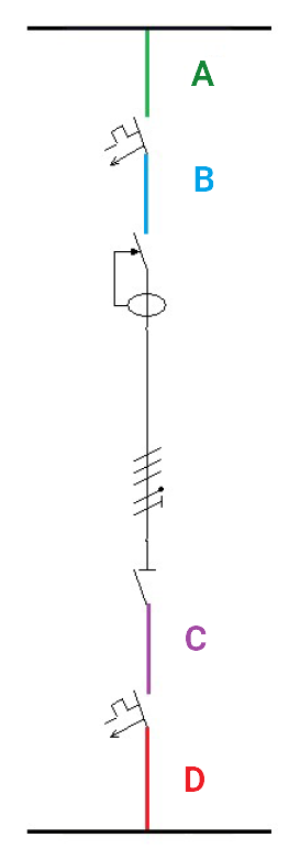
- Inlet (A)
They represent the sections of cable that supply the switchgear input of the line. Activating this option only makes sense when the input bridges of the lines start from a busbar located in the line immediately above. In this case, the busbar would act as a current distributor, causing the sections of the bridges (S1) to be reduced compared to the output bridge of the line above (S2).
- Between switchgear (B)
They represent the cable sections that connect elements of the same line arranged in series. Activating this option only makes sense if there are at least two devices for the same line in the same box.
Bridge lines of the bottom switchboard
- Between switchgear (C)
They represent the cable sections that connect elements of the same line arranged in series. Activating this option only makes sense if there are at least two devices for the same line in the same box.
- Outlet (D)
They represent the cable sections that connect the switchgear arranged at the output of the line with the elements that are located downstream of it (busbars, protection devices, manoeuvring elements, etc.).
Entering bridge lines
Bridge lines are entered in the program in the "Internal connections in the switchboard" section using the editing panel for groups, lines, circuits, switchboards, special lines and supplies. From here, users can activate the following checkboxes, which are available depending on the element being edited:
- Bridge lines of the top switchboard
- Bridge lines of the bottom switchboard
- Bridge lines (only in groups)
For greater clarity on the concept of bridge lines, this section includes an aid that details the different bridge lines that may be present in the switchboards that make up the electrical installation.
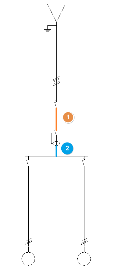
Use examples
In a diagram with a parent line and several child lines, the following options can be activated to define the bridge lines between the protections arranged in them:
- Bridge lines with no busbar
In a diagram without a busbar, simply edit the parent line and activate the two boxes "Between switchgear" (1), which represents the section between the protections of the parent line, and "Outlet" (2), which represents the section between the last protection of the parent line and the first protection of the child line, in its editing panel.
- Bridge lines with busbar
In a diagram with a busbar, both parent and child lines must be edited:- On the parent line, three boxes are activated: "Between switchgear" (1), which represents the section between its protections, "Outlet" (2), which represents the section between the last protection and the busbar, and "Busbar" (3).
- On each of the child lines, the "Inlet" box (4) is activated, which represents the section between the busbar and the first protection of the child line.
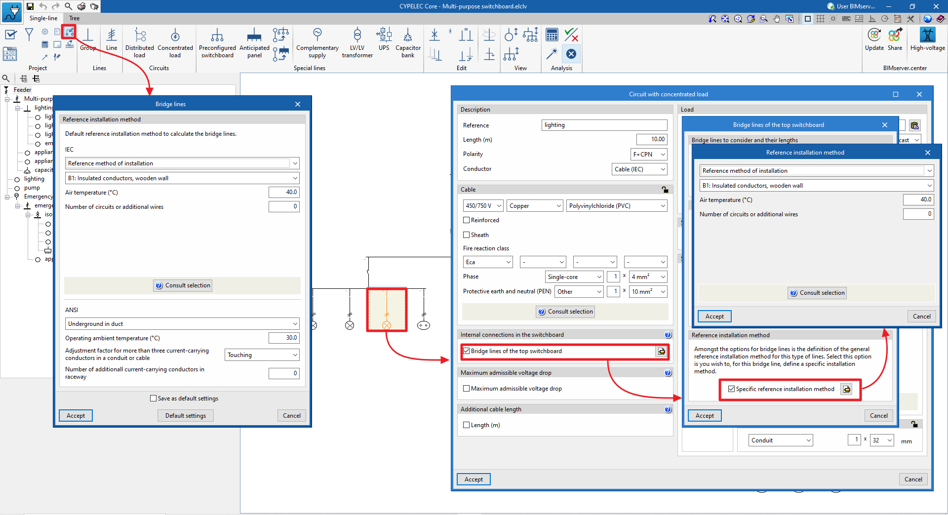
Reference installation method for bridge lines
In order to simplify the selection of the installation method on bridge lines, the "Bridge lines" option is available in the "Project" group of the general interface, where the default reference installation method to be considered for all bridge lines is selected.
If necessary, the reference installation method for the bridge lines of the switchgear to which they belong can be edited individually at a later date and in detail. To do this, access the bridge line via the "Internal connections in the switchboard" section of the element's editing panel and activate the "Specific reference installation method" option.
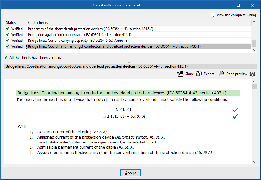
Checking bridge lines
Checks are carried out on the ampacity and coordination between conductors and the overload protection devices on the bridging lines so that the maximum admissible current of the cable forming the bridge line is above the rated current of the protection device protecting it.
Designing bridge lines
When designing the electrical installation, it is also possible to design the overload bridge lines (heating).
Furthermore, the bridge lines that have not been activated manually in each of the lines belonging to the electrical installation can be generated automatically with the "Generate bridge lines" option. Checking this option enables the design of the installation's bridge lines depending on the busbar layout (in which case the inlet lines to the protection devices will be activated) and the series connection of the switchgear (in which case the bridge lines between switchgear will be activated).
The default cable type and lengths assigned for the automatically generated bride lines are set in the "Design options" of the "Project" group.