Defining busbars
When high-power installations are planned, a series of copper or aluminium bars are usually placed at the inlet of the general control and protection panel or in the distribution of meters. These busbars are used to distribute the current to the protection of each line, which means that they withstand very high currents. It is therefore necessary to check the correct design of the bars, both for the thermal forces and for the mechanical forces that they will have to withstand.
Based on the properties of the installation as well as the busbar layout, the following checks are carried out:
- Minimum section for design current
- Increase of allowable temperature for short circuit current
- Mechanical resistance of the bars
- Mechanical resistance of the brackets
- Deformation of the bars
- Intrinsic resonant frequency
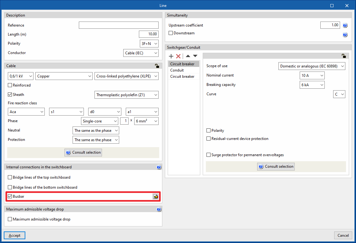
To use a busbar on the lines, in the "Internal connections in the switchboard" section of the entry or editing panel, the "Busbar" option must be selected.
This can be used to access a busbar entry assistant, which has four tabs: "Enter", "Installation", "Brackets" and "Bars":
“Enter” tab
This tab details the common use of busbars and the checks carried out on them in the program.

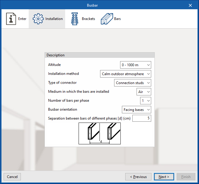
“Installation” tab
Allows users to describe the general parameters of the busbar installation:
- Description
- Altitude
- Installation method
- Type of connector
- Medium in which the bars are installed
- Number of bars per phase
- Busbar orientation
- Separation between bars of different phases [d] (cm)
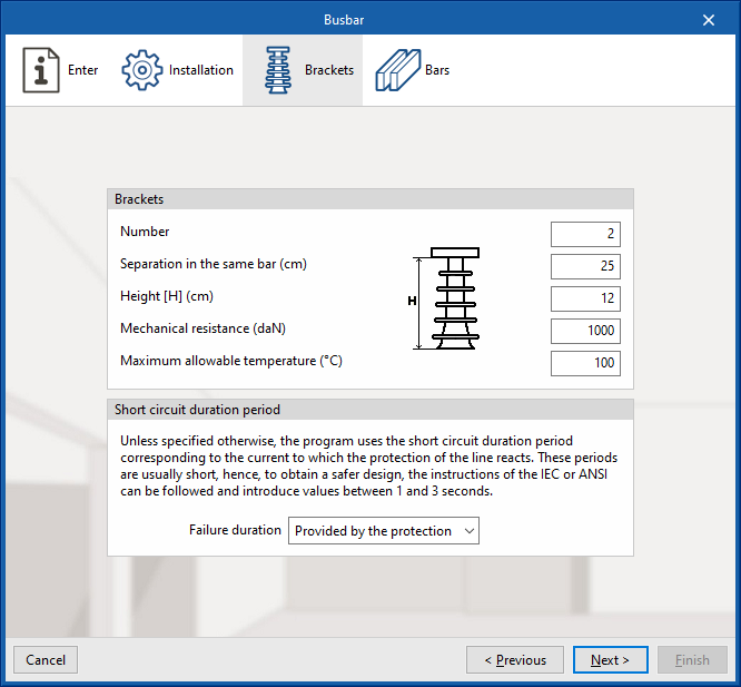
“Brackets” tab
The number, geometry and properties of the busbar brackets as well as the short-circuit duration time can be set:
- Brackets
- Number
- Separation in the same bar (cm)
- Height [H] (cm)
- Mechanical resistance (daN)
- Maximum allowable temperature (ºC)
- Short circuit duration period
Unless specified otherwise, the program uses the short circuit duration period corresponding to the current to which the protection of the line reacts. These periods are usually short, hence, to obtain a safer design, the instructions of the IEC or ANSI can be followed and introduce values between 1 and 3 seconds.- Failure duration (User defined (sec) / Provided by the protection)
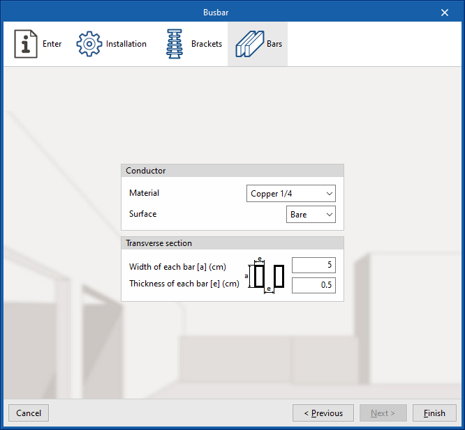
“Bars” tab
Allows the material, surface and section of the busbars to be adjusted:
- Conductor
- Material
- Surface (Bare / Painted)
- Transverse section
- Width of each bar [a] (cm)
- Thickness of each bar [a] (cm)
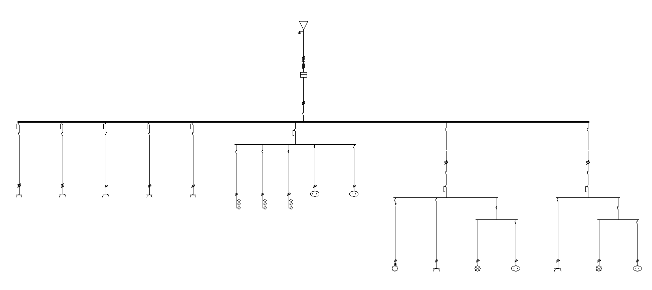
Once the busbar has been defined, the program represents it in the single-line diagram with a thicker horizontal line.