
Defining cables in lines and circuits
Cables can be defined in the "Cable" section, located on the left-hand side of the editing panels for lines, circuits, panels and special lines.
The definition options available in this section vary depending on whether a "Cable (IEC)" or "Cable (ANSI)" is defined in the "Conductor" option in the "Description" section of the line, circuit, switchboard or special line. They are as follows:
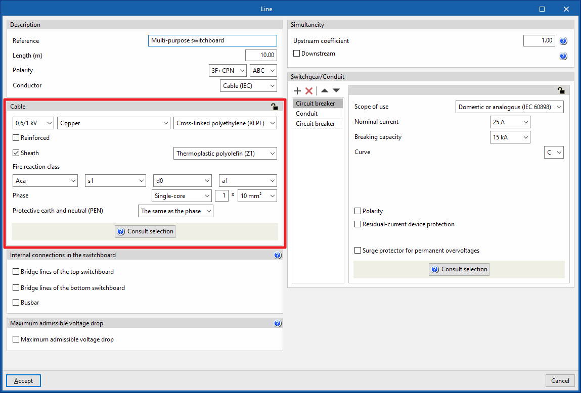
Defining IEC cables
If an IEC standard cable is defined, the program allows the following parameters to be configured:
- Nominal voltage (0,6/1 kV / 450/750 V / 300/500 V)
- Material (Copper/Aluminium)
- Insulation
- Reinforcement (optional)
- Selecting the reinforcement material
- Roof (optional)
- Selecting the reinforcement material
- Fire reaction class
- Phase
- Single-core / Multi-conductor
- Number of conductors per pole x Section of the conductor
- Neutral
This can be "The same as the phase" or "Other":- Single-core / Multi-conductor
- Number of conductors per pole x Section of the conductor
- Protection
This can be "The same as the phase", "Without conductor" ( if there is no need for the protective conductor distribution) or "Other":- Single-core / Multi-conductor
- Number of conductors per pole x Section of the conductor
- Protective earth and neutral (PEN)
Only available in polarity 3F + CPN, 2F + CPN or F + CPN. This can be "The same as the phase", "Without conductor" or "Other":- Single-core / Multi-conductor
- Number of conductors per pole x Section of the conductor
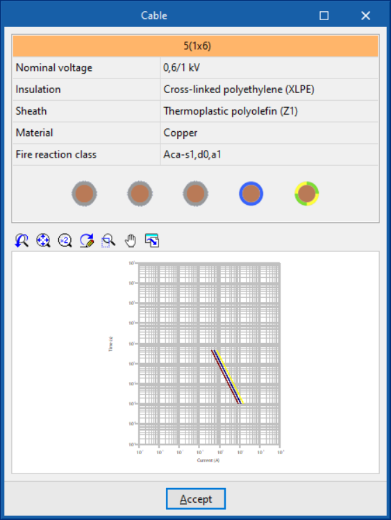
By clicking on the "Consult selection" option, a panel is displayed which provides clarification about the data entered, as well as a current-time graph of the thermal resistance of the cable.
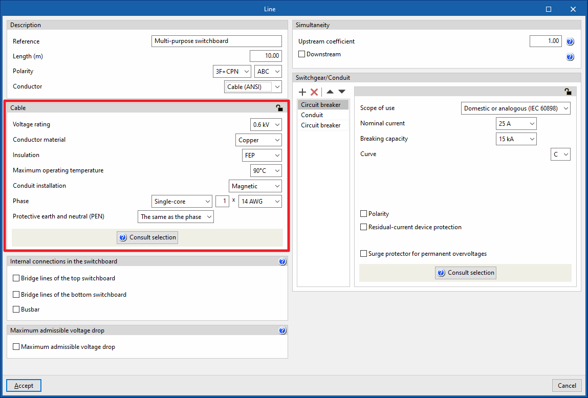
Defining ANSI cables
If a cable is defined under the ANSI standard, the program allows the following parameters to be configured:
- Voltage rating (0,6/1 kV / 450/750 V / 300/500 V)
- Conductor material (Copper / Aluminium)
- Insulation
- Maximum operating temperature
- Conduit installation (Magnetic / Not magnetic)
- Phase
- Single-core / Multi-conductor
- Number of conductors per pole x Section of the conductor
- Neutral
This can be "The same as the phase" or "Other":- Single-core / Multi-conductor
- Number of conductors per pole x Section of the conductor
- Protection
This can be "The same as the phase", "Without conductor" ( if there is no need for the protective conductor distribution) or "Other":- Single-core / Multi-conductor
- Number of conductors per pole x Section of the conduct
- Protective earth and neutral (PEN)
Only available in polarity 3F + CPN, 2F + CPN or F + CPN. This can be "The same as the phase", "Without conductor" or "Other":- Single-core / Multi-conductor
- Number of conductors per pole x Section of the conductor
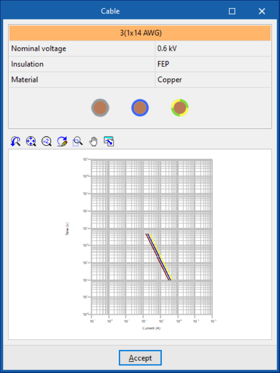
By clicking on the "Consult selection" option, a panel is displayed which provides clarification about the data entered, as well as a current-time graph of the thermal resistance of the cable.
The panel for defining the type of conduit and the installation method is also adapted to the cable selection made.
The program incorporates the grouping correction factor tables for all installation methods in accordance with IEC 60364-5-52. Some tables for certain installation methods may not provide a grouping correction factor for a large number of conductors, in which case the program uses the most unfavourable factor from the table and indicates this with a warning message in the ampacity test. This extension can be used for cables with more than 2500 A for transformer outgoing current, for example.