
Entering circuits
In the "Circuits" group of the main toolbar, either in the "Single-line" tab or in the "Tree" tab, the following elements can be defined and entered:

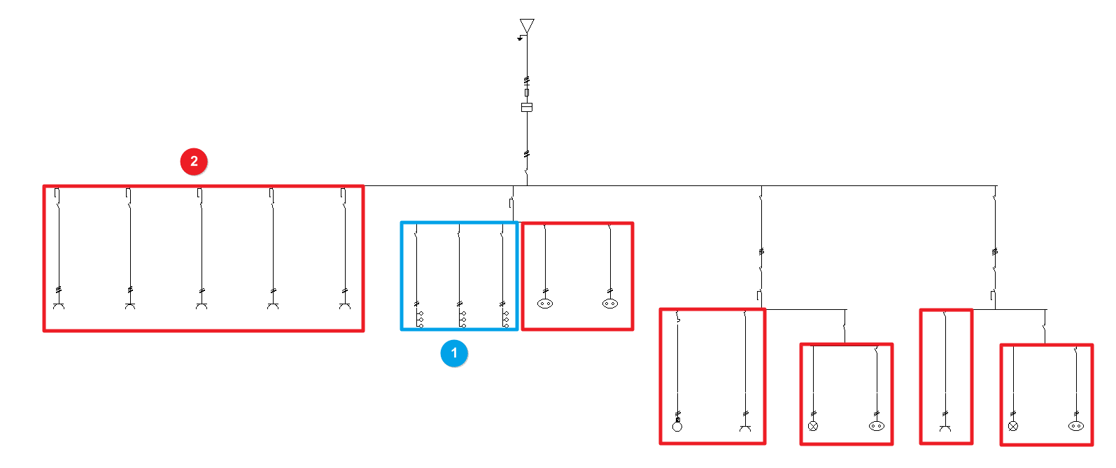
Both distributed and concentrated load circuits can be freely arranged in the single-line diagram on multiple levels:
- Circuits with distributed load (1)
- Circuits with concentrated load (2)
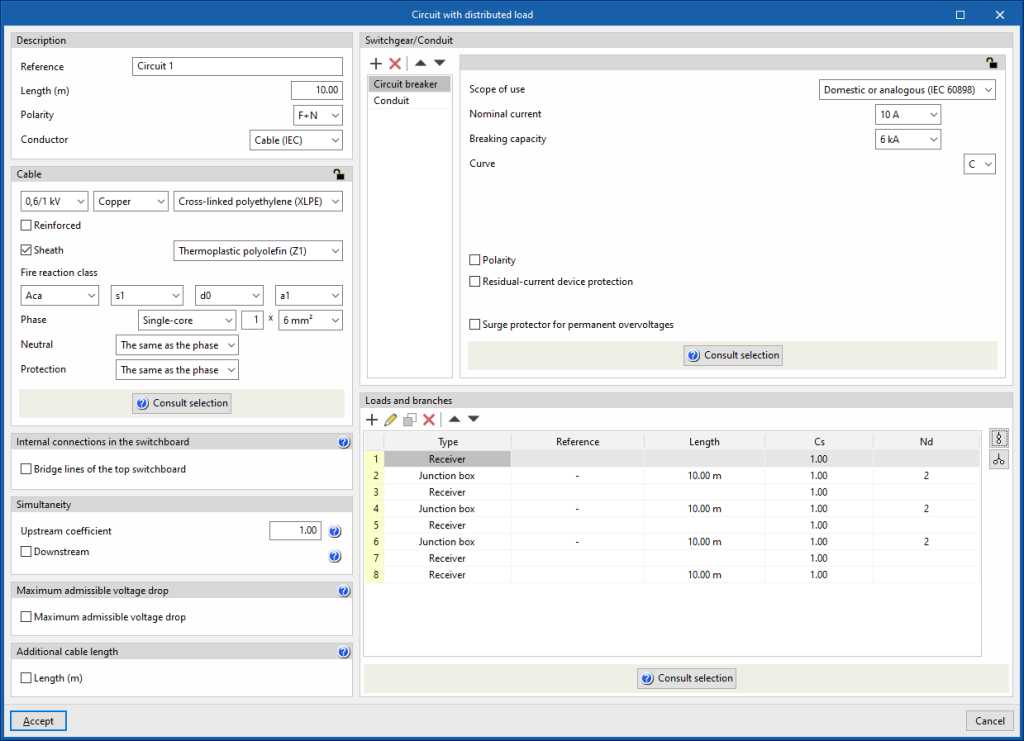
Circuit with distributed load
The "Distributed load" option allows users to define and enter a distributed load circuit. These circuits allow the load distribution to be detailed. Clicking on this option opens the "Circuit with distributed load" window, which displays the following configuration options:
- Description
- Reference
- Length (m)
- Polarity
- Conductor
- Cable (IEC)
- Precast conduit
- Cable (ANSI)
- Cable
- Internal connections in the switchboard
- Bridge lines of the top switchboard (optional)
By activating this option, the program allows users to enter and consider bridge lines at the top of the line. It opens the "Bridge lines of the top switchboard" window, with the following options:- Bridge lines to consider and their lengths
- Inlet (optional)
- Between switchgear (optional)
- Conductor
- Cable
- Reference installation method
- Specific reference installation method (optional)
- Bridge lines to consider and their lengths
- Bridge lines of the top switchboard (optional)
- Simultaneity
These options allow users to define the simultaneity of the lines. - Maximum admissible voltage drop
- Maximum admissible voltage drop (optional)
With this option, users can set a maximum admissible voltage drop value. The program will check and design the line according to the value entered.
- Maximum admissible voltage drop (optional)
- Additional cable length
With this option, users can enter a value that complements the circuit's length to measure the cable's total length. This length can consider, for example, the connection between junction boxes and switches to complete the lighting points, or the junction boxes that the circuit may include in its installation that have not been considered for the sizing of the cable, but are considered for its total measurement:- Length (m) (optional)
For example, for a large installation (such as an industrial building or a hospital) where the lighting is to be divided into sectors and where it is more convenient to enter a distributed load block to copy it several times and then make minor modifications to each one of them.
- Switchgear/Conduit
Allows the switchgear to be inserted and the line conduit to be defined. This can be of the following types:- Circuit breaker
- Fuse
- Magnetic starter
- Residual-current device
- Surge protector for transient overvoltages
- Sectionaliser
- Switch disconnector
- Contactor
- Network analyser
- Capacitor
- Battery
- Loads and branches
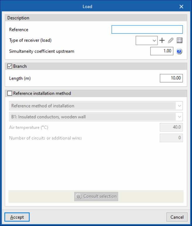
This table can be used to enter loads, junction boxes and transition nodes to model the geometry of the load distribution. Different reference installation methods can be defined for each of the sections that make up the conduit of a circuit with distributed load:- Load
- Description
- Reference
- Type of receiver (load)
- Simultaneity coefficient upstream
- Branch (optional)
- Length (m)
- Specific reference installation method (optional)
- Description
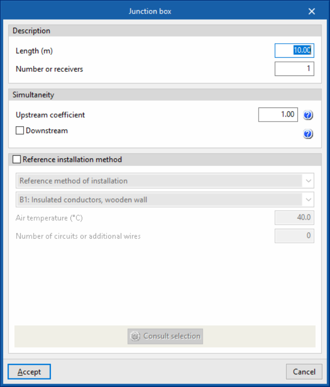
- Junction box
- Description
- Length (m)
- Number of receivers
- Simultaneity
- Upstream coefficient
- Downstream (optional)
- Specific reference installation method (optional)
- Description
- Transition node
- Automatic generation of loads and derivations
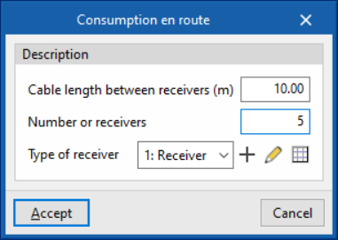
The program has help assistants on the right-hand side to automatically generate the set of loads, junction boxes and transition nodes of the distributed load circuit in the following cases:- Consumption en route
This generates a distributed en-route load, using junction boxes to distribute the load across the receivers along the route spaced a distance equal to the indicated length:- Cable length between receivers (m)
- Number of receivers
- Polarity (only in three-phase supply lines)
- Type of receiver (load)
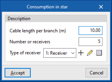
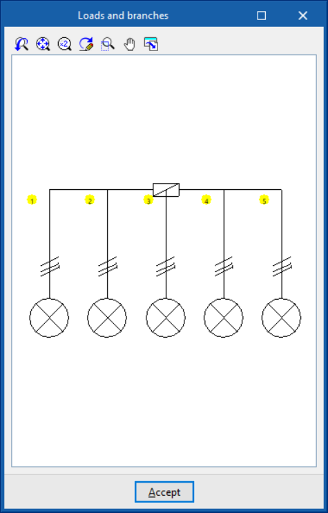
- Consumption in star
This generates a star-shaped distributed load. From the initial node, it generates as many branches as there are receivers.- Cable length per branch (m)
- Number or receivers
- Polarity (only in three-phase supply lines)
- Type of receiver (load)
- Consumption en route
- Load
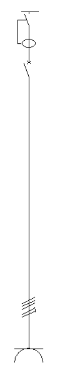
The load definition panels, junction boxes and transition nodes look as follows:

On the other hand, the automatic load generation assistants and derivations in the cases of consumption en route and consumption in star are shown as follows:
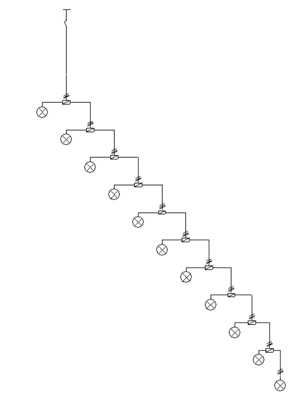
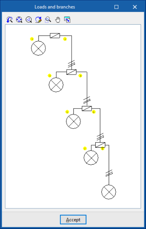
Using "Check selection", a representation of the load distribution diagram in the circuit is displayed. The location of the junction boxes used in distributed load circuits is represented by their standardised icon:
Circuit with concentrated load
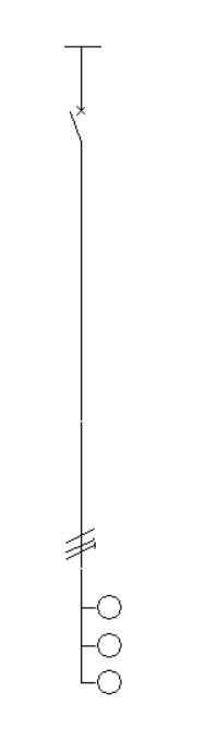
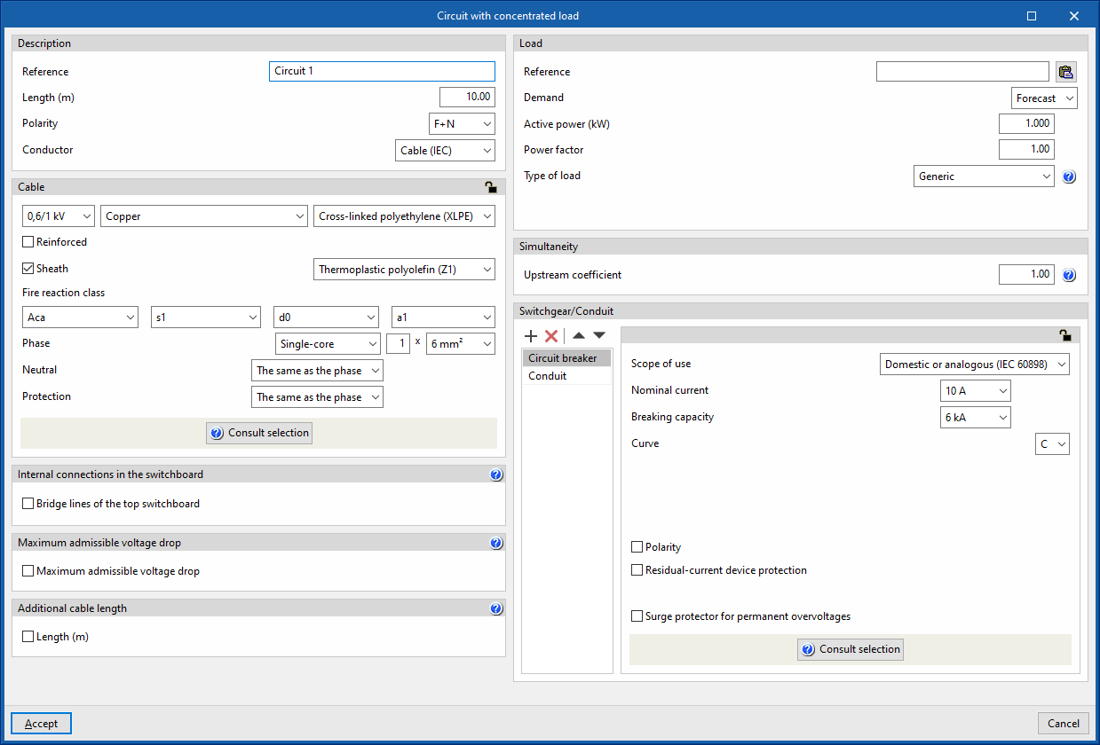
The "Concentrated load" option allows users to define and enter a concentrated load circuit. These circuits ensure that the entire load is concentrated at a point at a certain distance equal to the indicated length. Clicking on the option opens the "Circuit with concentrated load" window, which displays the following configuration options:
- Description
- Reference
- Length
- Polarity
- Conductor
- Cable (IEC)
- Precast conduit
- Cable (ANSI)
- Cable
- Internal connections in the switchboard
- Bridge lines of the top switchboard (optional)
By activating this option, the program allows users to enter and consider bridge lines at the top of the line. It opens the "Bridge lines of the top switchboard" window, with the following options:- Bridge lines to consider and their lengths
- Inlet (optional)
- Between switchgear (optional)
- Conductor
- Cable
- Reference installation method
- Specific reference installation method (optional)
- Bridge lines to consider and their lengths
- Bridge lines of the top switchboard (optional)
- Maximum admissible voltage drop
- Maximum admissible voltage drop (optional)
With this option, users can set a maximum admissible voltage drop value. The program will check and design the line according to the value entered.
- Maximum admissible voltage drop (optional)
- Additional cable length
With this option, users can enter a value that complements the length of the circuit for the purposes of the total cable measurement. This length can consider the connection between junction boxes and switches to complete the light points, for example, or the junctions that the circuit may include in its installation that have not been considered for the sizing of the cable, but are taken into account for its total measurement:- Length (m) (optional)
- Load
This allows the concentrated load of the circuit to be defined. This load can be entered as a forecast or by choosing one of the types of receivers defined in the element library.- Reference
A reference can be entered for the load feeding the circuit, both for cases where the demand is defined by forecast and for cases where it is defined by the receiver. In the latter case, the reference is complementary to the reference given to the electrical receiver itself.
The load reference can be typed in directly or, using the corresponding button, copied from the circuit reference, if both are to be the same. - Demand: "Forecast"
This is used when a preliminary design of the installation is being carried out in which only an expected power for the line is to be quantified. The following must be defined:- Active power (kW)
- Power factor
- Type of load
The type of load describes the nature of the element that the circuit is intended to supply. This can be as follows:- Lighting
- Emergency
- General use outlet
- Motor
The selection of this type of load implies that the connection conductors are to be sized for a current of 125 % of the full load current of the motor. - Electric vehicle charging
- Generic
- Demand: "Receiver"
In this case, users would be fully aware of the element to be placed in the installation, and choose it from the receivers library:- Type of receiver
The configuration and selection of the receiver type in the library allows the following data to be automatically displayed:- Type of load
- Power supply (Single-phase/Three-phase)
- Active power (kW)
- Type of receiver
- Reference
- Simultaneity
These options allow users to define the simultaneity of the lines. - Switchgear/Conduit
Allows the switchgear to be inserted and the conduit of the line to be defined. This can be of the following types:- Circuit breaker
- Fuse
- Magnetic starter
- Residual-current device
- Surge protector for transient overvoltages
- Sectionaliser
- Switch disconnector
- Contactor
- Network analyser
- Capacitor
- Battery