Defining the project characteristics
In the "Project" group of the main toolbar, in either the "Single-line" tab or the "Tree" tab, the following project data can be defined:

These options allow users to set the project's general characteristics, the supply conditions and the libraries of elements used, to adjust the analysis and design, and to adjust the presentation of the information on the screen and the drawings.
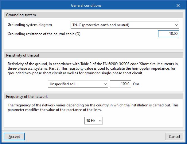
General conditions
When clicking on this button, a panel is displayed where the general conditions of the job can be established, which will be used to determine the starting points for the analyses to be carried out by the program.
Grounding system
Allows users to define the grounding system diagram and the parameters that characterise it:
- Grounding system diagram
- TT (neutral to ground)
- TN-S (grounded neutral)
- TN-C-S (protective earth and neutral)
- TN-C-S (protective earth and neutral in a part of the diagram)
- IT (unearthed neutral)
- IT (impedant neutral)
- Grounding resistance of the exposed conductive parts (in TT and IT diagrams)
- Grounding resistance of the neutral cable (in TT, TN-S, TN-C and TN-C-S diagrams)
- Neutral resistance (in IT diagrams)
The numerical values of the grounding resistance of the system can be imported from the BIM model based on the data entered in programs such as CYPELEC Grounding IEC and CYPELEC Grounding IEEE, and shared with the BIMserver.center project. The program updates the value of the grounding resistance of the exposed conductive parts or neutral cable, depending on the program that has generated the project's IFC:
- IFC generated by CYPELEC Grounding IEC
IFCs generated from programs that analyse low voltage grounding such as CYPELEC Grounding IEC update the grounding resistance of the exposed conductive parts. - IFC generated by CYPELEC Grounding IEEE
IFCs generated from programs that analyse high voltage grounding such as CYPELEC Grounding IEEE update the grounding resistance of the neutral cable.
Resistivity of the soil
This allows the resistivity of the ground to be defined according to Table 2 of the EN 60909-3: 2003 code "Short circuit currents in three-phase a.c. systems. Part 3". This value is used to calculate the homopolar impedance. The following can be defined:
- Type of soil (Unspecified soil; Granite; Rock; Stony ground; Pebbles, dry sand; Calcareous ground, damp sand; Agricultural soil; Clay, mud; Marshland)
- Resistivity of the soil (Ω⋅m)
Frequency of the network
This value varies depending on the country where the installation is carried out. The parameter entered modifies the reactance of the lines. This allows users to choose between the following frequencies:
- 50 Hertz
- 60 Hertz
The TN-C-S diagram is unique because the TN-C and TN-S diagrams are combined in a single system. The program carries out the special checks that this combination entails ("no TN-C scheme downstream of the TN-S scheme, no residual current device downstream of the connection of the protective earth conductor to the CPN conductor").
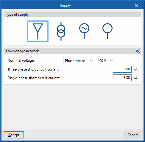
Supply
Type of supply
This dialogue box allows the program to define the type of main supply for the system. The following options are offered:
- Low voltage network
This allows a low-voltage network to be defined as the main supply. The nominal voltage to be used must be established, as well as the three-phase and single-phase short-circuit currents, from which the short-circuit impedances of the installation will be determined. Default indicative values are assigned, which are normally provided by the distribution company, but which can be adjusted. These values are:- Rated voltage (Phase-neutral / Phase-phase) (V)
- Three-phase short circuit current (kA)
- Single-phase short circuit current (kA)
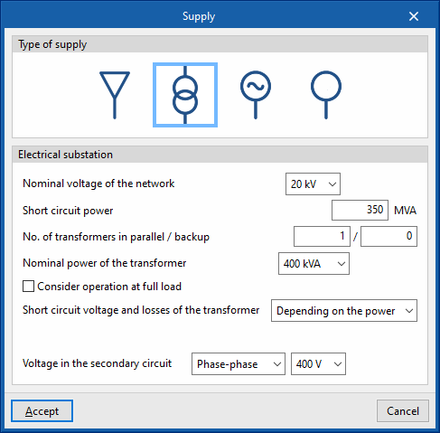
- Electrical substation
Allows users to define a transformer substation as the main supply. The following data can be indicated:- Nominal voltage of the network (kV)
- Short circuit power (MVA)
- No. of transformers in parallel /backup
- Nominal power of the transformer (kVA)
- Consider operation at full load (optional)
With this option, the calculation current of the transformer line is obtained from its rated power, instead of taking the power of the loads it feeds. - Short circuit voltage and losses of the transformer (Depending on the power / User-defined)
- Voltage in the secondary circuit (Phase-neutral / Phase-phase) (V)
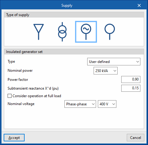
- Insulated generator set
Allows users to define a stand-alone generator set as the main supply. The following data can be entered:- Type:
- User-defined:
- Nominal capacity (kVA)
- Power factor
- Subtransient reactance X''d (pu)
- Manufacturer generator set
- User-defined:
- Consider operation at full load (optional)
- Rated voltage (Phase-neutral / Phase-phase) (V)
- Type:
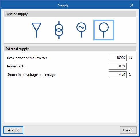
- External supply
With this option, any type of main supply can be defined generically. The following data can be entered:- Peak power of the inverter (VA)
- Power factor
- Short circuit voltage percentage (%)
Library elements
Allows users to check and edit the libraries of the following elements of the system:
- Preconfigured switchboards
- Types of receivers
- Prefabricated conduits
- Groups of lines
- Manufacturer generator sets
Each of the element types can be imported and exported to files on disk in a single command. After selecting the elements to be imported, they will be added to the library and placed after the existing ones or, if they are the same, they will replace them.

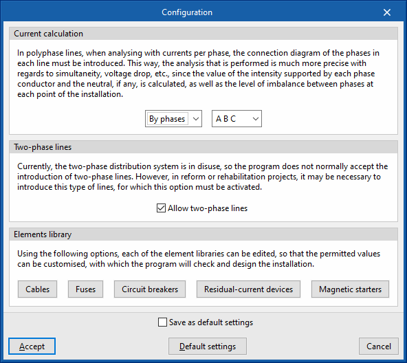
Configuration
Current calculation
Allows users to choose between a balanced or phase-by-phase calculation of currents:
- Balanced
In this mode, the three single phase phases attached to a three-phase line are assumed to be balanced. This way of proceeding may be more convenient for design purposes, but it is only an approximation, as total balance is very difficult to achieve. - By phases
This mode offers users the possibility of designing the system with an unbalanced phase distribution. The program allows the nomenclature of the phases of a three-phase electrical system to be selected in several ways:- R S T / A B C / L1 L2 L3 / U V W / X Y Z / R Y B / R G B
When selecting "By phases", for polyphase lines, the phase connection diagram for each line must be selected.
This way, the analysis is more precise, since the current value in each phase conductor and the neutral cable is calculated, as well as the imbalance level between phases at any point of the system if it exists. The currents flowing through each of the phases and the neutral cable to compensate for the imbalance between them will be taken into account, these currents will be considered when correctly designing the section of each conductor (including the neutral cable) and both the simple voltage drops (phase-to-neutral) and the compound voltage drops (phase-to-phase) will be calculated.
Two-phase lines
Allows users to activate the possibility of defining two-phase lines in the system. Although the two-phase distribution system is no longer in use, this can be useful in refurbishment or renovation projects.
- Allow two-phase lines (optional)
This ensures that, both in the supply line and the intermediate lines, the three-wire distribution is activated (2F + N or 2F + CPN), and that in the final circuits with loads the two-wire supply is activated (2F or 2F+CPN), as well as allowing the definition of two-phase electrical receivers. If the calculation is made "By phases", the program will also allow the two-phase selection in RS, ST or TR.
Elements library
Allows users to customise the permitted values of the following elements to allow their definition in the model or to use them for design purposes. The parameter selection in the line editing panels is conditioned by the editing of the element libraries so that the elements that have not been selected will remain hidden in the line editing:
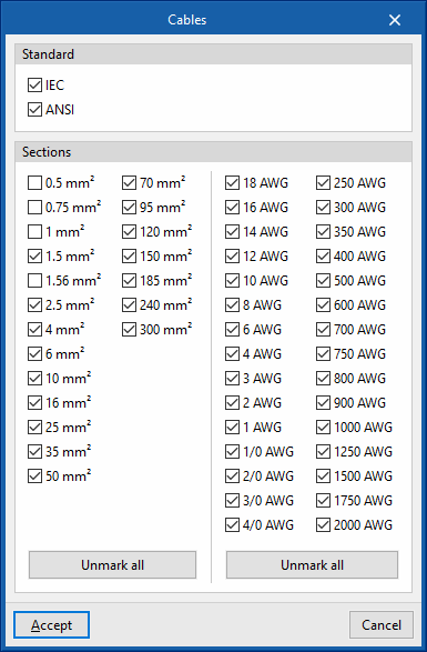
- Cables
- Standard (IEC / ANSI)
- Sections
Cables under the IEC standard in mm2 can be used, or cables under the ANSI standard in American Wire Gauge (AWG).
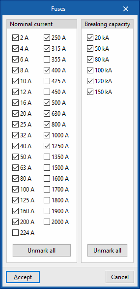
- Fuses
- Nominal current
- Breaking capacity
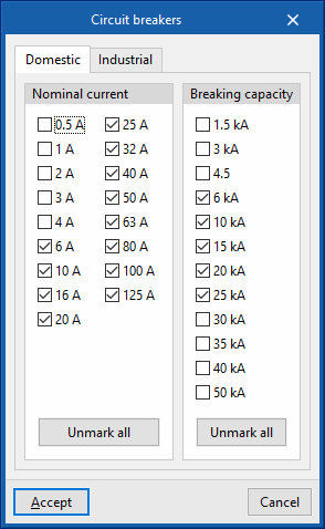
- Circuit breakers
- “Domestic” tab
- Nominal current
- Breaking capacity
- “Industrial” tab
- Nominal current
- “Domestic” tab
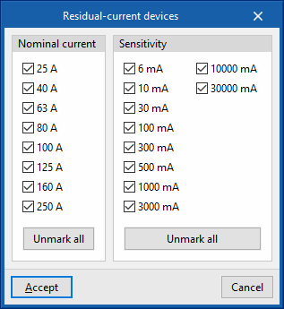
- Residual-current devices
- Nominal current
- Sensitivity
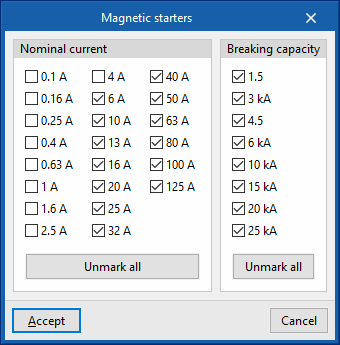
- Magnetic starters
- Nominal current
- Breaking capacity
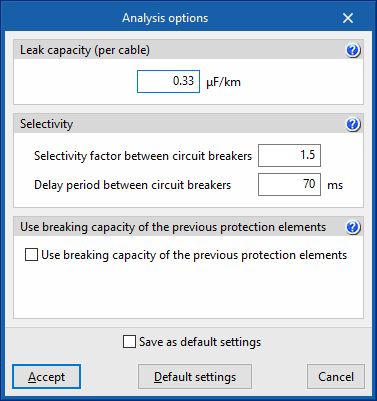
Analysis options
Leak capacity (per cable)
This section enters the earth leakage capacitance value of a cable (μF/km). This value is used to estimate the leak currents when testing the sensitivity of the residual current circuit breakers installed as protection against indirect contacts.
Selectivity
To carry out the selectivity check, the program allows the following parameters to be defined:
- Selectivity factor between circuit breakers
- Delay period between circuit breakers (ms)
The selective action between the overcurrent protection devices is checked by analysing their corresponding firing curves (curve selectivity). The firing times and the currents for which the disconnection of the devices connected in series takes place must have, depending on the type of device, the corresponding safety interval.
Use breaking capacity of the previous protection elements
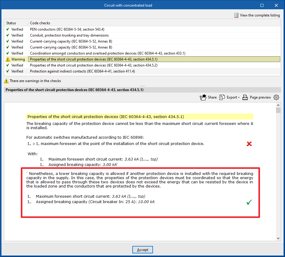
IEC 60364-4-43, section 434.5.1. allows a lower breaking capacity of the load zone protective device if another upstream protective device with the required breaking capacity is installed on the supply side.
To consider this, the following options can be marked:
- Use breaking capacity of the previous protection elements (optional)
- Of the fuses (optional)
- Of the circuit breakers (optional)
In this case, the characteristics of the two devices must be coordinated (e.g. by applying screening techniques) so that the energy allowed to pass through these two devices does not exceed the energy that can be withstood without damage by the device in the load zone and the conductors protected by the devices.
The check report will include a comment if this option has been used.
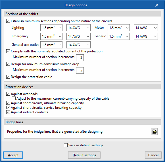
Design options
Sections of the cables
PAllows users to configure the criteria to be considered in the automatic design process carried out by the program for the cable sections. Users can carry out the following:
- Establish minimum sections depending on the nature of the circuits (optional)
- Lighting
- Emergency
- General use outlet
- Motor
- Generic
- Comply with the nominal/regulated current of the protection (optional)
Allows the cable section to be increased to comply with the rated current or regulated current of the protection (IB≤In≤Iz check), by specifying the maximum number of section increments that the program will perform automatically:- Maximum number of section increments
- Design for maximum admissible voltage drop (optional)
Design for maximum admissible voltage drop, specifying the maximum number of section increments that the program is to perform automatically. This criteria considers the limitation of the "Maximum admissible voltage drop" imposed by the user in the edition panel of the groups, lines and circuits:- Maximum number of section increments
- Design the protection cable (optional)
Protection devices
Allows users to configure the criteria to be considered in the automatic design process carried out by the program for the installation's protection devices. The following options can be activated:
- Against overloads (optional)
Designs the overload protection devices, with the added possibility of adjusting the rated current of the protection to the maximum admissible current of the cable:- Adjust to the maximum current-carrying capacity of the cable (optional)
- Against short circuits, ultimate breaking capacity (optional)
Designs short-circuit protection devices to ultimate breaking capacity. - Against short circuits, service breaking capacity (optional)
Designs short-circuit protection devices to service breaking capacity. - Against indirect contacts (optional)
Designs the rating of protective devices against indirect contacts.
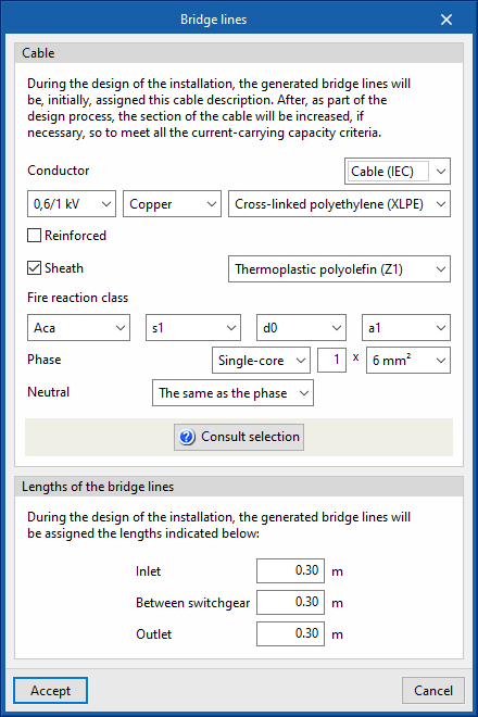
Bridge lines
Allows users to define the characteristics of the bridge lines generated when designing the system.
- Properties for the bridge lines that are generated after designing
- Cable
When designing the system, the bridge lines generated are assigned the cable description selected in this section. Subsequently, as part of the design process, the cable section shall be increased, if necessary, to meet the current-carrying capacity criteria. - Lengths of the bridge lines
When designing the system, the generated bridge lines shall be assigned the lengths indicated below:- Inlet
- Between switchgear
- Outlet
- Cable
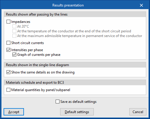
Results presentation
Allows users to configure the presentation of the results obtained by the program in the following ways:
- Results shown after passing by the lines
- Impedances (optional)
- At 20 ºC (optional)
- At the temperature of the conductor at the end of the short circuit period (optional)
- At the maximum admissible temperature in permanent service of the conductor
- Short circuit currents (optional)
- Intensities by phase (optional)
These options are useful when working in the current per-phase calculation mode.- Graph of currents per phase (optional)
- Impedances (optional)
- Results shown in the single-line diagram
- Show the same details as on the drawing (optional)
- Material schedule and export to BC3
- Material quantities by panel/subpanel (optional)
With this option, users can launch the material table report not only in a global form for the project but also classified by panels and subpanels.
- Material quantities by panel/subpanel (optional)
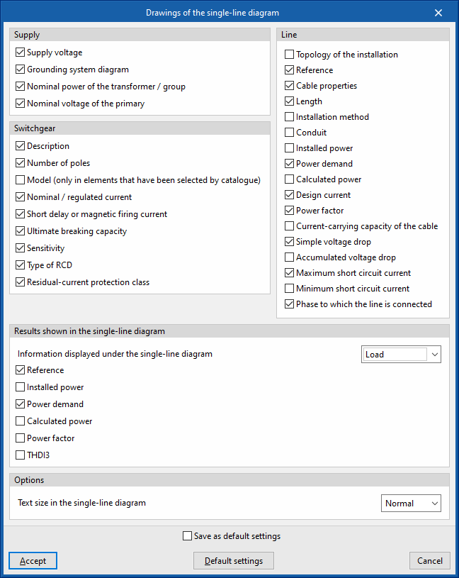
Drawings of the single-line diagram
Allows you to activate or deactivate the information shown in the single-line diagram drawings for each of the following elements:
- Supply (Supply voltage, Grounding system diagram, Nominal power of the transformer / group, Nominal voltage of the primary)
- Load (Reference, Installed power, Power demand, Calculated power, Power factor, THDI3)
- Switchgear (Description, number of poles, Model (only in elements that have been selected by catalogue, Nominal / regulated current, Short delay or magnetic firing current, Ultimate breaking capacity, Sensitivity, Type of RCD, Residual-current protection class)
- Line (Topology of the installation, Reference, Cable properties, Length, Installation method, Conduit, Installed power, Power demand, Calculated power, Design current, Power factor, Current-carrying capacity of the cable, Simple voltage drop, Accumulated voltage drop, Maximum short circuit current, Minimum short circuit current, Phase to which the line is connected)
Users can also modify and configure the results information displayed at the bottom of the single-line diagram. This information can be displayed under the electrical load or as a properties table. To update these values after modifying the editing data, users must click on the "Analysis" option:
- Results shown in the single-line diagram
- Information displayed under the single-line diagram
- Load (Reference, Installed power, Power demand, Calculated power, Power factor, THDI3)
- Properties table (Reference, Installed power, Power demand, Calculated power, Nominal voltage, Design current, Current-carrying capacity of the cable, Cable properties, Length, Simple voltage drop, Accumulated voltage drop)
- Information displayed under the single-line diagram
Finally, the program allows users to configure the following options:
- Options
- Text size in the single-line diagram
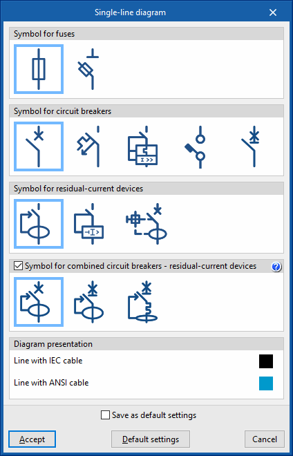
Single-line diagram
Allows users to configure the symbology used by the program in the single-line diagram for different types of protections, as well as the lines' representation colour:
- Symbol for fuses
- Symbol for circuit breakers
- Symbol for residual-current devices
- Symbol for combined circuit breakers - residual-current devices (optional)
This option allows the combined combined circuit breaker - residual-current device to be represented by a single symbol combining both features, instead of being represented by two separate symbols. - Diagram presentation
This allows the colour of the lines to be chosen according to the cable used. Lines with mm2 or AWG wires can thus be distinguished in the same electrical system:- Line with IEC cable
- Line with ANSI cable
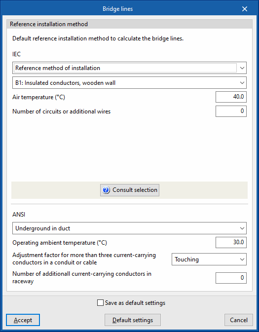
Bridge lines
Reference installation method
This section defines the default reference installation method for analysing bridge lines, specifying its characteristics for both IEC and ANSI cables.
- IEC:
- Reference method of installation / IEC 60364-5-52, Table A.52.3
- Ambient temperature
- Number of circuits or additional wires
- ANSI:
- Reference method of installation
- Operating ambient temperature
- Adjustment factor for more than three current-carrying conductors in a conduit or cable
- Number of additional current-carrying conductors in the same conduit
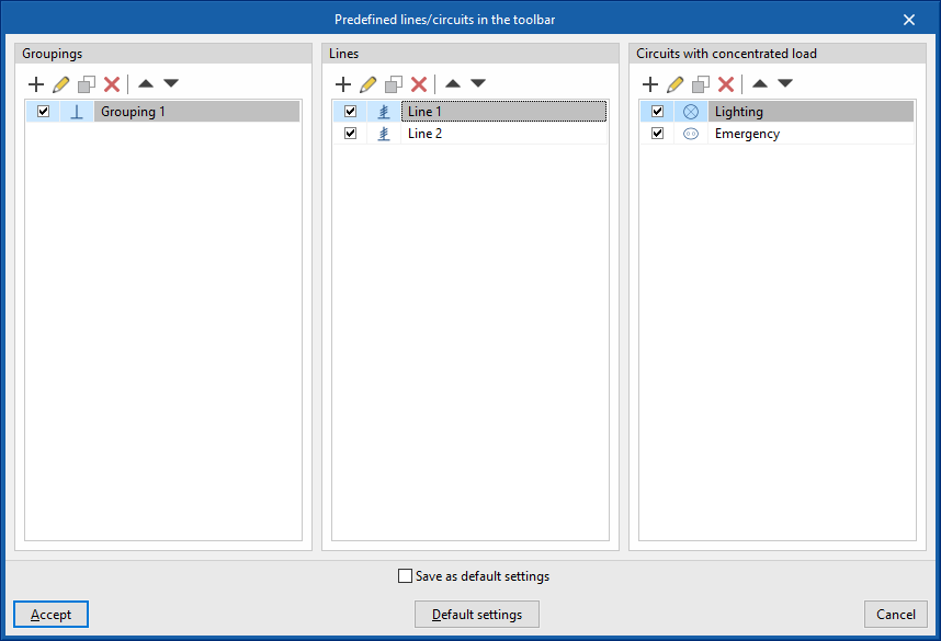
Predefined lines/circuits in the toolbar
This option provides several tables in which lines or circuits with predetermined properties can be defined and configured, indicating an icon and a reference for each one of them.
These predefined lines or circuits will appear as new options in the top toolbar of the program interface. This means that more or fewer buttons with their corresponding icons will appear on the toolbar depending on the user's settings.
The aim of this feature is to speed up the entry of installation data, enabling quick access to be generated for the most frequently used lines or circuits.
Predefined lines or circuits can be defined for the following types of elements:
- Groupings
- Lines
- Circuits with concentrated load