Entering special lines
In the "Special lines" group of the main toolbar, either in the "Single-line" tab or in the "Tree" tab, the following elements can be defined and entered:

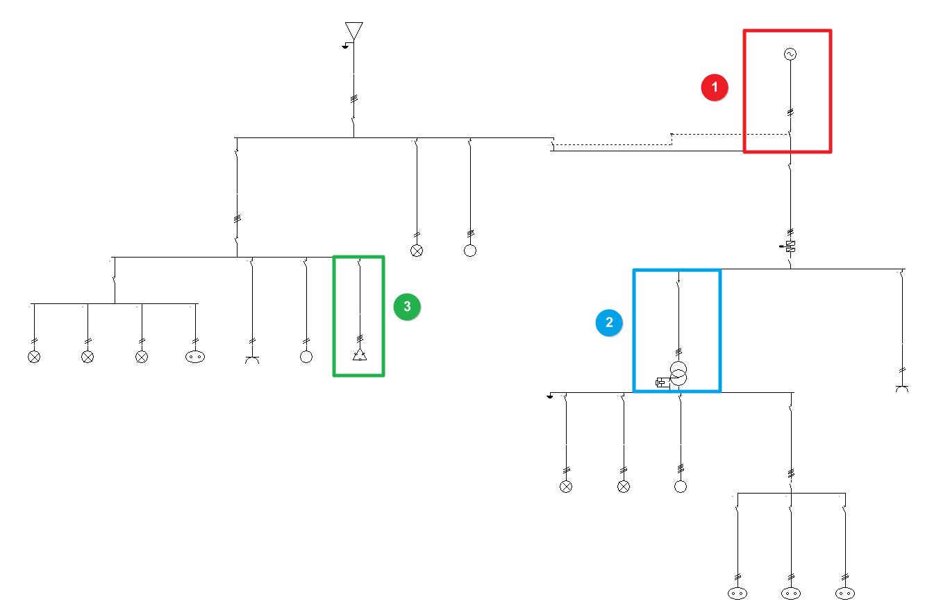
The program offers great versatility when it comes to placing special lines in the single-line diagram of the electrical installation:
- Complementary supply (1)
- LV/LV transformer (2)
- Capacitor bank (3)
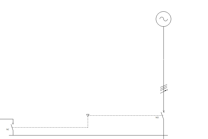
Complementary supply
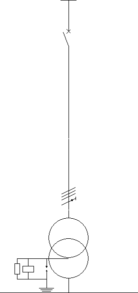
This option allows users to add an additional complementary supply corresponding to a generator set, in addition to the ordinary supply defined in the "Supply" option of the "Project" group.
The complementary supply through a generator set can provide service to the whole installation, to part of the installation or to start up the emergency services deemed appropriate in the event of failure of the normal supply.
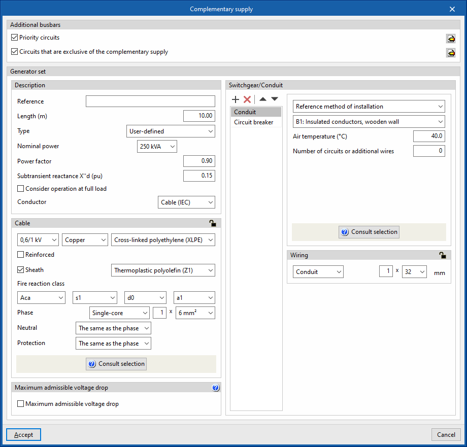
Clicking on the option opens the "Complementary supply" window, which allows the following parameters to be configured:
- Additional busbars
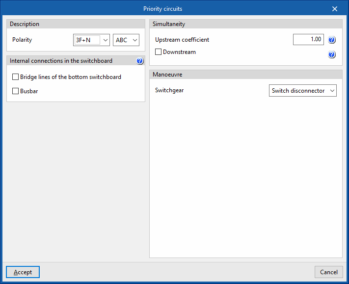
In this section, users can specify the existence of priority circuits or circuits that are exclusive of the complementary supply:- Priority circuits (optional)
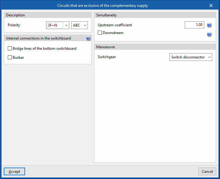
Allows users to define priority circuits that are fed by both the ordinary supply and the complementary supply. - Circuits that are exclusive of the complementary supply (optional)
Allows users to define priority circuits that are fed by both the ordinary supply and the complementary supply.
Both options can be activated, thus having both priority circuits and exclusive circuits. The rest of the circuits, neither priority nor exclusive, will be powered only by the ordinary supply.
When activating any of these options, the program displays a window in which these circuits are configured, including the following data:- Description
- Polarity
- Internal connections in the switchboard
- Bridge lines of the bottom switchboard
- Busbar
- Simultaneity
- Manoeuvre
- Switchgear (Switch disconnector / Circuit breaker / Contactor)
- Description
- Priority circuits (optional)
- Generator set
In this section, users will find the details of the generator set, as well as the cable, switchgear and conduit of the line corresponding to the complementary supply:- Description
- Reference
- Length
- Type:
- User defined
- Nominal capacity
- Power factor
- Subtransient reactance X''d (pu)
- Manufacturer generator set
- User defined
- Consider operation at full load (optional)
- Conductor
- Cable (IEC)
- Precast conduit
- Cable (ANSI)
- Cable
- Switchgear/Conduit
By default, this includes:- Conduit
- Circuit breaker
- Description
LV/LV transformer
This option allows users to add an intermediate low-voltage-low-voltage transformer along the length of the installation.
This allows the nominal voltage to be raised or lowered, as is the case with the use of a transformer for installations supplied at very low safety voltage (MBTS).
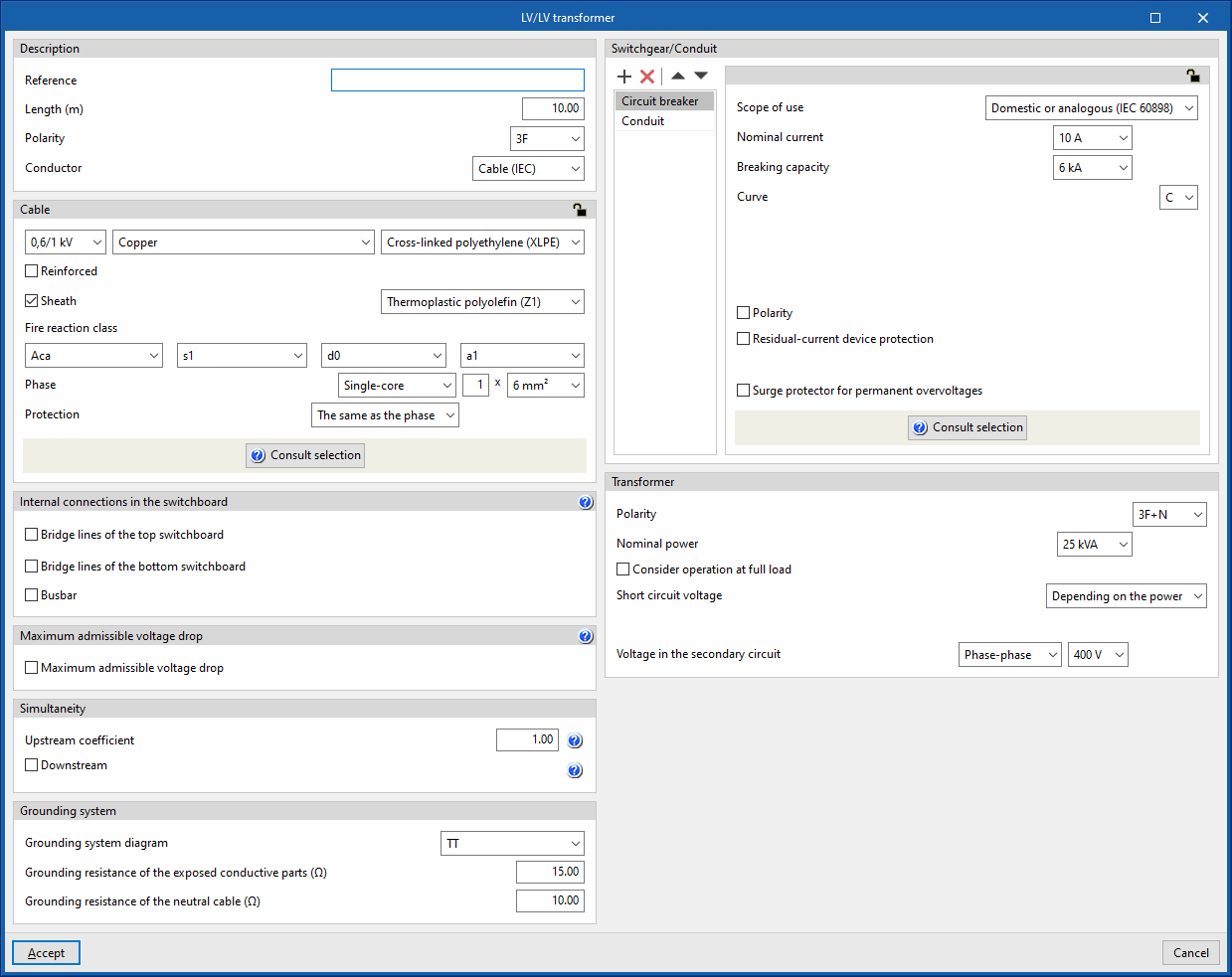
Clicking on this option opens the "LV/LV transformer" window, which allows the following parameters to be configured:
- Description
- Reference
- Length
- Polarity
- Conductor
- Cable (IEC)
- Precast conduit
- Cable (ANSI)
- Cable
- Internal connections in the switchboard
- Bridge lines of the top switchboard (optional)
- Bridge lines of the bottom switchboard
- Busbar (optional)
- Maximum admissible voltage drop
- Maximum admissible voltage drop (optional)
- Simultaneity
- Switchgear/Conduit
By default, this includes:- Circuit breaker
- Conduit
- Transformer
This section provides details of the transformer data as well as the secondary winding voltage:- Polarity
- Nominal power (kVA)
- Consider operation at full load (optional)
With this option, the calculation current of the transformer line is obtained from its rated power, instead of taking the power of the loads it feeds. - Short circuit voltage (Depending on the power / User defined (%, kW))
- Voltage in the secondary circuit (Phase-neutral / Phase-phase) (V)
UPS (Uninterruptible power supply)
This option allows a UPS ( Uninterruptible power supply) to be added to the installation. These systems guarantee the power supply in the event of mains power failure through the use of batteries.
Clicking on it opens the "UPS" window, which allows the following parameters to be configured:
- Description
- Polarity
- Busbar
- Simultaneity
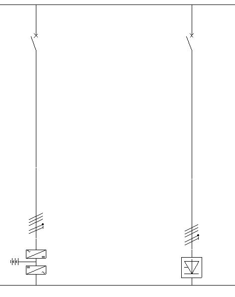
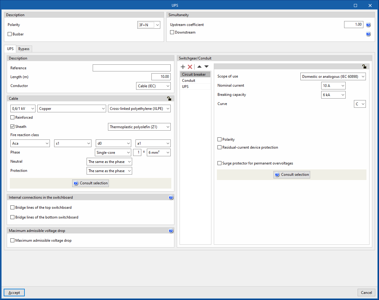
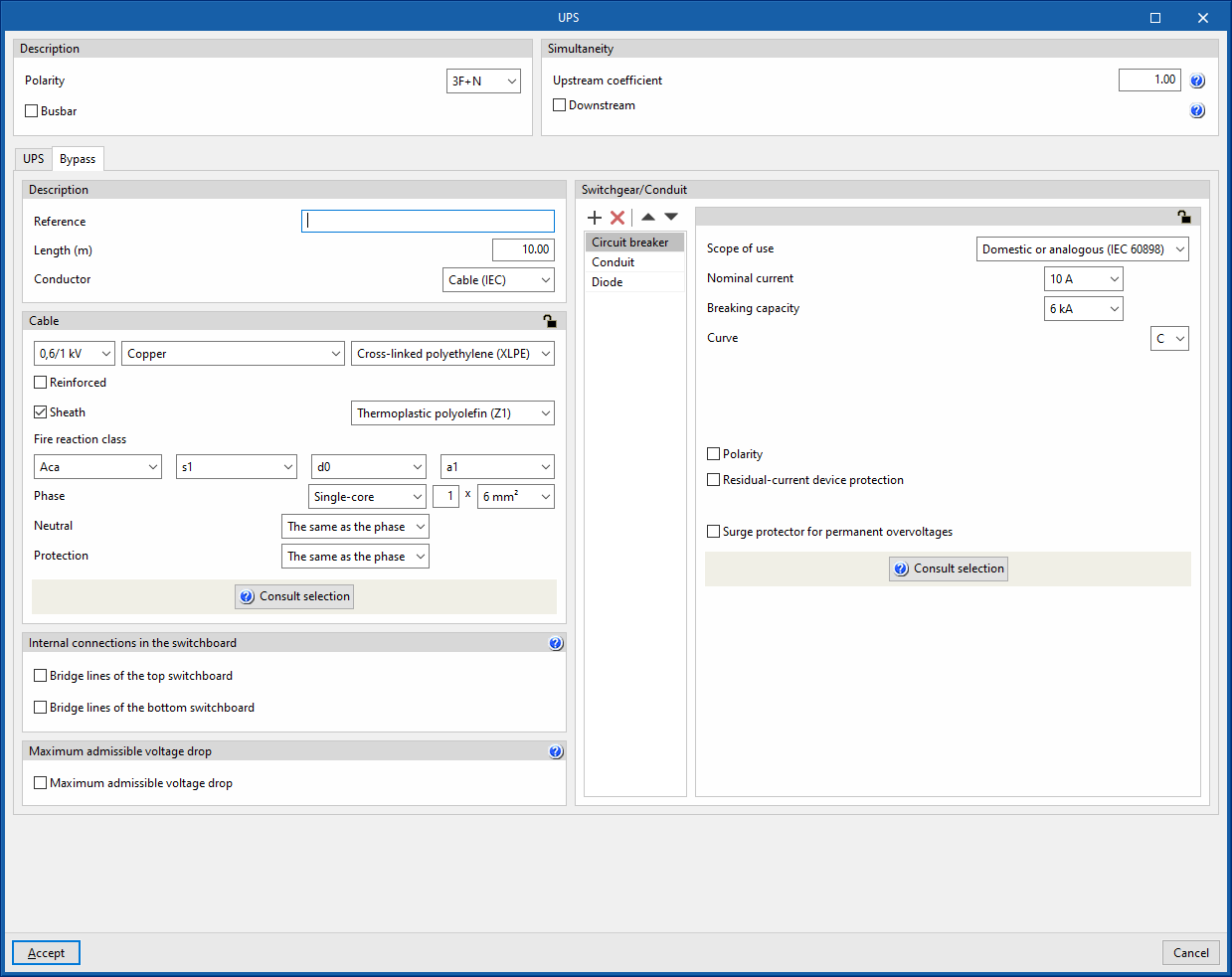
The UPS group consists of two lines, which are detailed in the editing window through two tabs, "UPS" and "Bypass":
- "UPS" tab
This corresponds to the main line. It contains the rectifier, the batteries and the inverter. - “Bypass” tab
Corresponds to the bypass line and allows normal battery-free operation.
Each of the lines operates as an independent element, with its own protection elements, analyses and the corresponding checks for correct operation. The following configuration options appear in each one of them:
- Description
- Reference
- Length
- Conductor
- Cable
- Internal connections in the switchboard
- Bridge lines of the top switchboard (optional)
- Bridge lines of the bottom switchboard (optional)
- Maximum admissible voltage drop
- Maximum admissible voltage drop (optional)
- Switchgear/Conduit
By default, this includes:- Circuit breaker
- Conduit
- UPS (in the main line)
- Power
- Power factor
- Short circuit contribution factor
- THDI3
- Diode (in the bypass line)
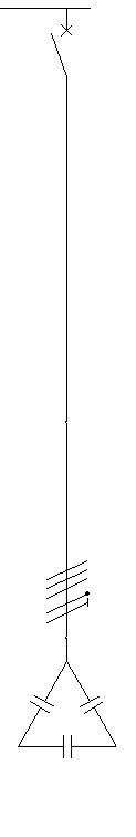
Capacitor bank
This option allows a capacitor bank to be added to the installation. The capacitor bank can be installed to improve the power factor of a group of circuits collectively. This is useful in installations where the resulting power factor is less than 1.
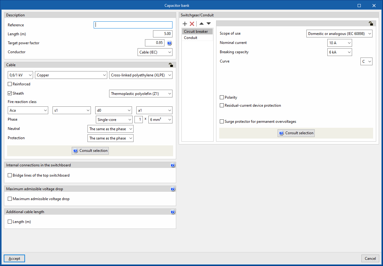
Clicking on it opens the "Capacitor bank" window, which allows the following parameters to be configured:
- Description
- Reference
- Length (m)
- Target power factor
- Conductor
- Cable
- Internal connections in the switchboard
- Bridge lines of the top switchboard (optional)
- Maximum admissible voltage drop
- Maximum admissible voltage drop (optional)
- Additional cable length
With this option, users can enter a value that supplements the circuit length for the total cable measurement. This is not taken into account for the design:- Length (m)
- Switchgear/Conduit
By default, this includes:- Circuit breaker
- Conduit