Entering switchboards
In the "Special lines" group of the main toolbar, either in the "Single-line" tab or in the "Tree" tab, there are tools for inserting frames into the program:

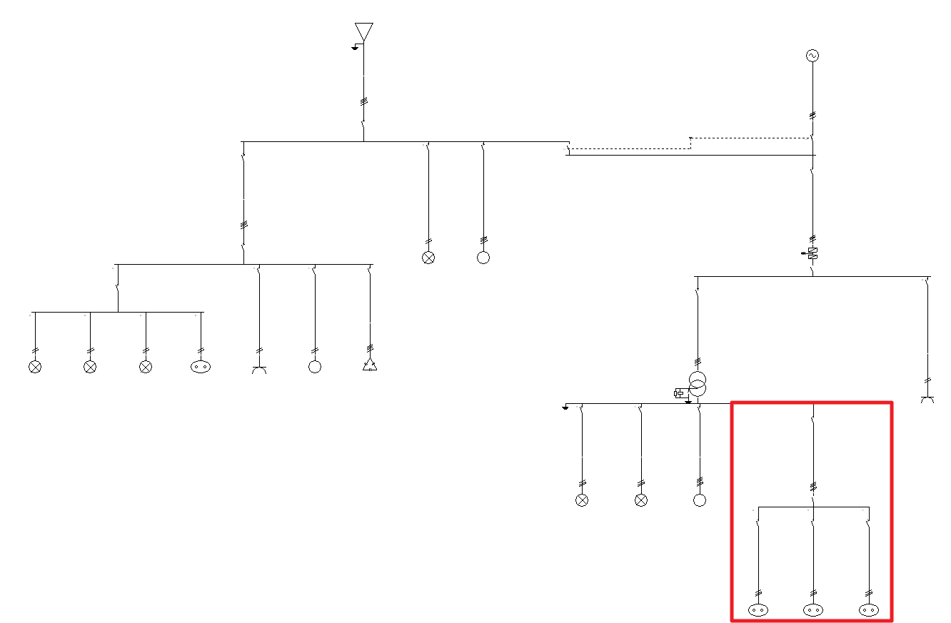
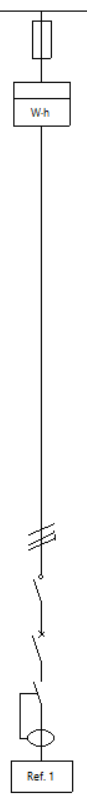
In the single-line diagram of the electrical installation, switchboards have a final position equivalent to that of a circuit or a set of groups, lines and circuits.
Preconfigured switchboard
Preconfigured switchboards are electrical switchboards with user-defined characteristics, which can be created and entered multiple times in the project. Editing a type of typified switchboard modifies the characteristics of all the switchboards entered associated with that type, which speeds up the work. This is useful if the installation has a large number of switchboards with the same characteristics.
Creating preconfigured switchboards
The definition of the typified tables available in the library of each job can be done through the "Project" group in the general interface toolbar, then selecting the "Element libraries" option.
The options available in the panel for creating preconfigured switchboards are as follows:
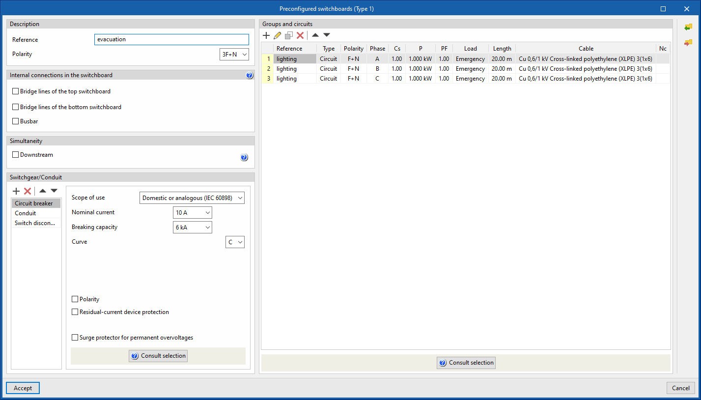
- Description
- Reference
- Polarity
- Internal connections in the switchboard
- Bridge lines of the top switchboard (optional)
By activating this option, the program allows users to enter and consider bridge lines at the top of the line. It opens the "Bridge lines of the top switchboard" window, with the following options:- Bridge lines to consider and their lengths
- Inlet (optional)
- Between switchgear (optional)
- Conductor
- Cable
- Reference installation method
- Specific reference installation method (optional)
- Bridge lines to consider and their lengths
- Bridge lines of the bottom switchboard (optional)
By activating this option, the program allows users to enter and consider bridge lines at the top of the line. It opens the "Bridge lines of the top switchboard" window, with the following options:- Bridge lines to consider and their lengths
- Inlet (optional)
- Outlet (optional)
- Conductor
- Cable
- Reference installation method
- Specific reference installation method (optional)
- Bridge lines to consider and their lengths
- Busbar
By activating this option, the program allows users to enter and consider busbars on the line.
- Bridge lines of the top switchboard (optional)
- Simultaneity
- Downstream (optional)
- Switchgear/Conduit
Allows users to enter the switchgear and define the conduits of the line. By default, this includes:- Conduit
- Groups and circuits
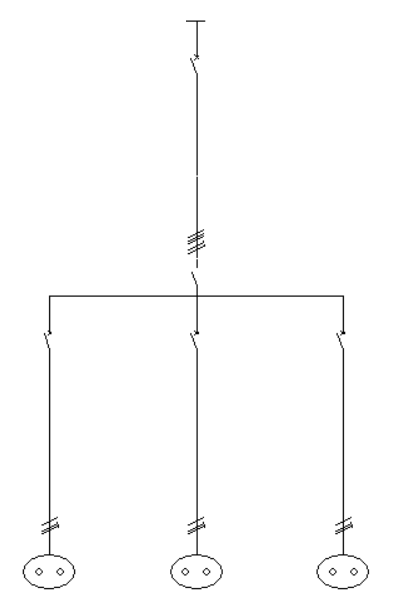
This is used to define the groups and circuits that make up the standardised table. The program displays a table in which these groups and lines can be added, edited, deleted or reordered. Clicking on "Circuit" opens the panel for editing circuits of concentrated loads and clicking on "Group" displays the corresponding panel. From "Consult selection", a partial single-line diagram of the groups and lines of the preconfigured switchboard is displayed. The following information is displayed:- Reference
- Type (Group /Circuit)
- Cs (upstream simultaneity coefficient)
- P (active power) (only in circuits)
- PF (power factor) (only in circuits)
- Load (only in circuits)
- Length (only in circuits)
- Cable (only in circuits)
- Nc (number of lines downstream) (only in groups)
Entering preconfigured switchboards
Then, to use a preconfigured switchboard, select the "Preconfigured switchboard" option in the "Special lines" group of the general interface toolbar.
The following parameters can be defined in the input window of the standard table:
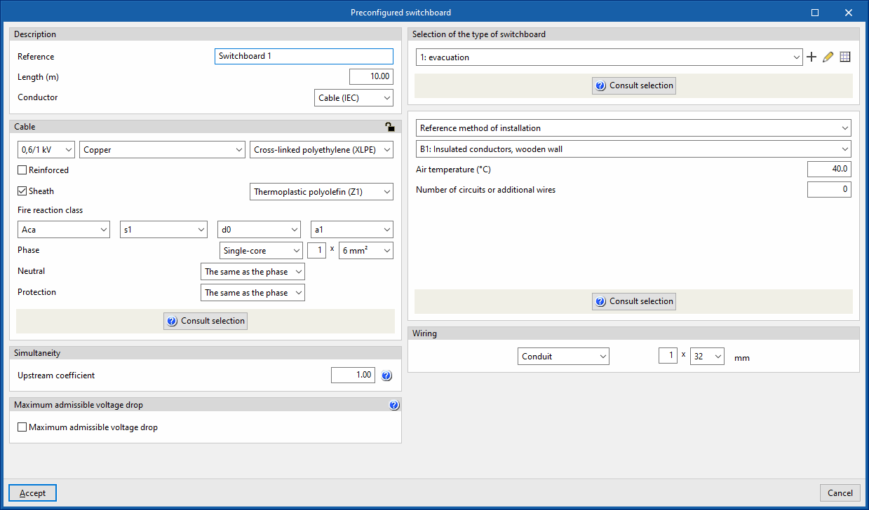
- Description
- Reference
- Length (m)
- Conductor
- Cable (IEC)
- Precast conduit
- Cable (ANSI)
- Cable
- Simultaneity
- Upstream coefficient
- Maximum admissible voltage drop
- Maximum admissible voltage drop (optional)
Con esta opción es posible fijar un valor de caída de tensión With this option, users can set a maximum admissible voltage drop value. The program will check and design the line according to the value entered.
- Maximum admissible voltage drop (optional)
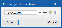
- Selection of the type of switchboard
Allows users to select a preconfigured switchboard created in the element libraries or to create it directly. - Conduit
Allows users to define the conduit of the line.
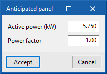
Anticipated pane
This allows users to represent a power supply line to a switchboard or sub-switchboard with a simplified load forecast, without the need to detail the internal groups and circuits. This line functions as a final line.
Clicking on the option opens the "Anticipated panel" window, which displays the following configuration options:
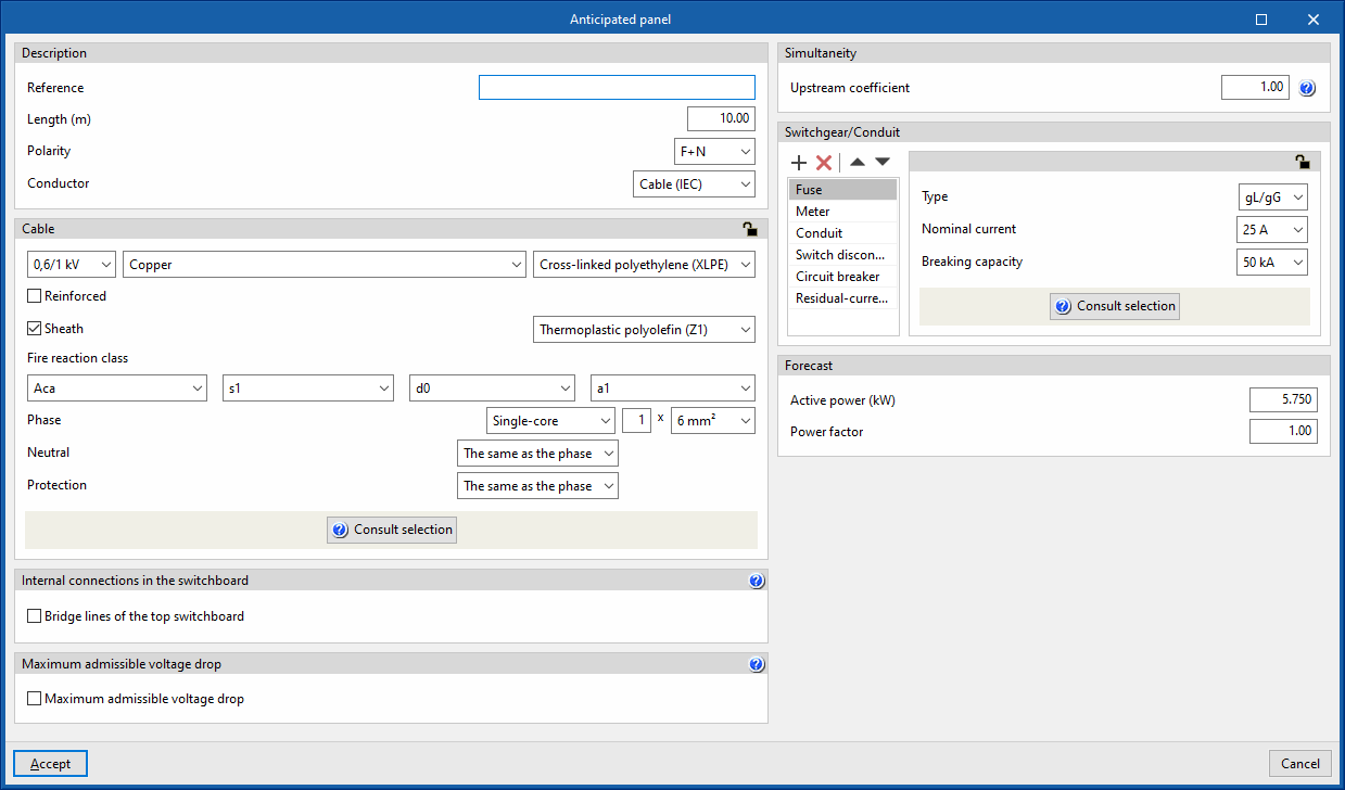
- Description
- Reference
- Length (m)
- Polarity
- Conductor
- Cable
- Internal connections in the switchboard
- Bridge lines of the top switchboard (optional)
By activating this option, the program allows users to enter and consider bridge lines at the top of the line. It opens the "Bridge lines of the top switchboard" window, with the following options:- Bridge lines to consider and their lengths
- Inlet (optional)
- Between switchgear (optional)
- Conductor
- Cable
- Reference installation method
- Specific reference installation method (optional)
- Bridge lines to consider and their lengths
- Bridge lines of the top switchboard (optional)
- Maximum admissible voltage drop
- Maximum admissible voltage drop (optional)
With this option, users can set a maximum admissible voltage drop value. The program will check and design the line according to the value entered.
- Maximum admissible voltage drop (optional)
- Simultaneity
- Upstream coefficient
- Switchgear/Conduit
Allows the switchgear to be entered and the line conduit to be defined. By default, it includes the following:- Fuse
- Meter
- Conduit
- Switch disconnector
- Circuit breaker
- Residual-current device
- Forecast
Allows users to define the power forecast of the switchboard by giving the following data:- Active power (kW)
- Power factor
Replacing lines with switchboards
The program has several options that allow users to replace lines previously entered in the diagram with preconfigured switchboards or tables by forecast:
Replace line with preconfigured switchboard
Allows users to select a line in the diagram and replace it with a preconfigured switchboard defined in the element library.
Substitute line with anticipated panel
Allows users to select a line in the diagram and replace it with an anticipated panel. This requires the definition of the following parameters:
- Active power (kW)
- Power factor