Work environment
The CYPELEC Core interface has two tabs at the top that allow users to access work environments that represent the system differently: "Single-line" and "Tree". Both work environments can be used to define the low-voltage electrical system, as the information entered is shared between the two tabs.
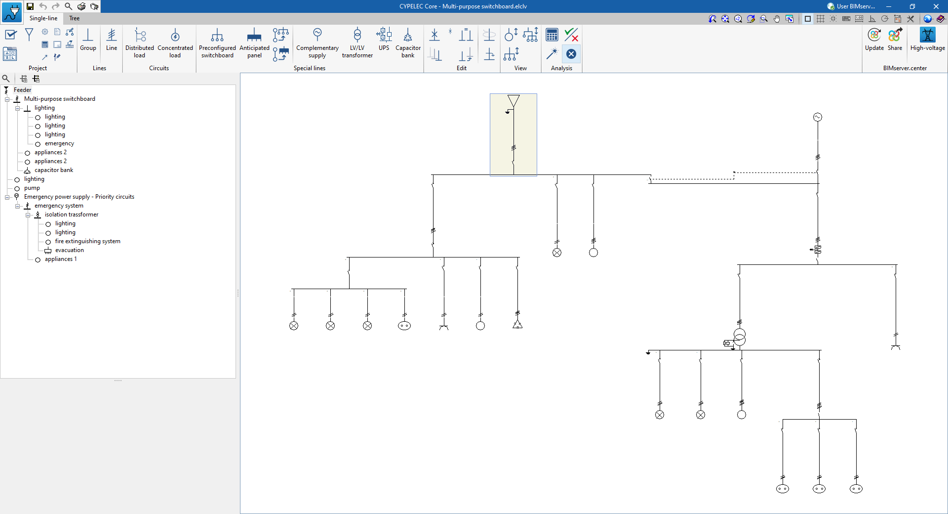
“Single-line” tab
When starting, the tab activated by default is the "Single-line" tab. This presents a work environment that allows users to design and analyse the low-voltage electrical system by directly viewing and editing its single-line diagram.
This tab displays the following:
- A top toolbar containing the tools for managing the general conditions, supply and other project options, such as options for entering and editing lines and circuits, and special switchboard and lines, for using the editing and viewing tools, and for carrying out the analysis, checking and design of the system.
- The single-line diagram display area, on the right-hand side of the screen, where the lines and components of the electrical system can be selected, viewed and edited.
- On the left-hand side, a tree structure of the lines and circuits making up the electrical system, which can be expanded or collapsed.
Also, by double-clicking on a line in the tree diagram, it is possible to access its editing panel.
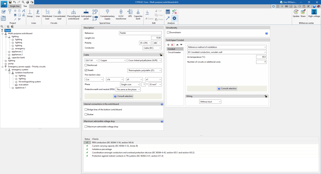
“Tree” tab
On the other hand, the "Tree" tab presents a work environment that allows users to design and analyse the low-voltage electrical system by directly accessing the panels for defining the lines and components from the project's navigation tree diagram.
This tab displays the following:
- A top toolbar containing the tools for managing the general conditions, supply and other project options, such as options for entering and editing lines and circuits, and switchboards and special lines, for using the editing tools and for analysing, checking and designing the system.
- The data editing panels of the lines and components of the electrical system, on the right-hand side of the screen.
- On the left-hand side, a tree structure of the lines and circuits that make up the electrical system can be expanded or contracted.