Managing the elements included in the project
In the "Project" section of the main toolbar, you will find the option to view the details of the elements already entered in the project:

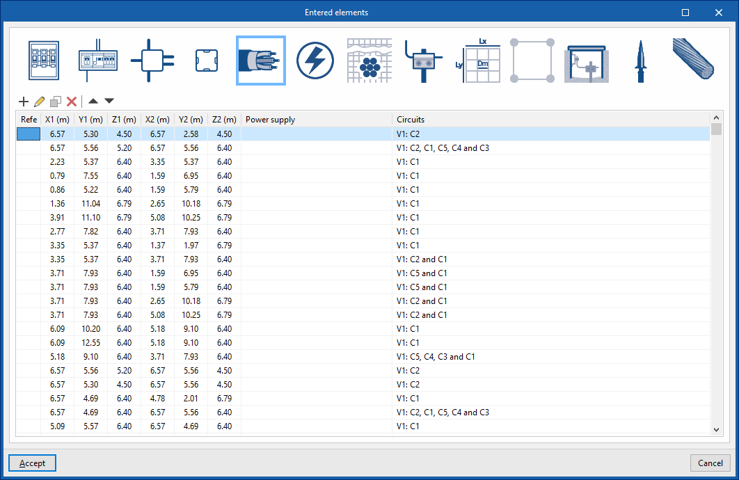
Elements entered
Checks and edits the details of the elements added to the model in a series of tables containing the following information:
- Link nodes: reference, X, Y, Z, angle, node type, feed (upstream)
- Switchboards: reference, X, Y, Z, angle, circuits, power supply (upstream)
- Junction boxes: reference, X, Y, Z, angle
- Pattress boxes: reference, X, Y, Z, angle
- Conduits: reference; X1, Y1, Z1 (coordinates of the starting point); X2, Y2, Z2 (coordinates of the end point); supply; circuits
- Receivers: reference, X, Y, Z, angle, box, circuit, description
- IEC buried conductor: reference; X1, Y1, Z1 (coordinates of the starting point); X2, Y2, Z2 (coordinates of the end point)
- IEC electrode: type, X, Y, Z, angle X, angle Y, angle Z
- IEEE grid: reference, X, Y, Z, X angle, Y angle, Z angle
- UNESA grid: reference, X, Y, Z, angle X, angle Y, angle Z
- Grounding box: reference, X, Y, Z, angle X, angle Y, angle Z
- Capture devices: reference, X, Y, Z, X angle, Y angle, Z angle
- Shunts or grounding conductors: reference; X1, Y1, Z1 (coordinates of the starting point); X2, Y2, Z2 (coordinates of the end point)