Grounding system diagram
The "Grounding" section of the main toolbar contains the tools for representing grounding systems in the building's geometric model:

The grounding systems that can be represented are those defined by the following types:
- IEC 60364-5-54
- IEEE Std 80-2000
- UNESA
Grounding systems are defined using the "Grounding systems" option in the "Project" group, whilst the tools in the "Grounding" group allow for their geometric input and graphical representation.
The options in this section are as follows:
- "Layout" menu
Includes the options "IEC buried conductor", "IEC electrode", "IEEE mesh" and "UNESA mesh". - "Box" option
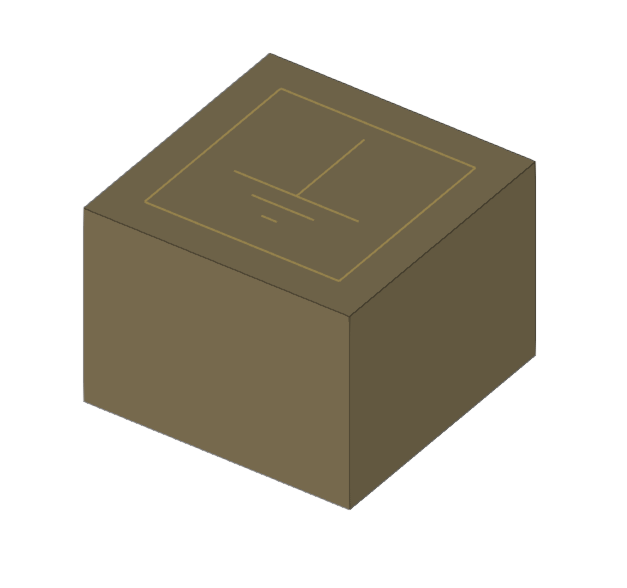
Inserts manholes for earth connections.
The options mentioned are set out below:
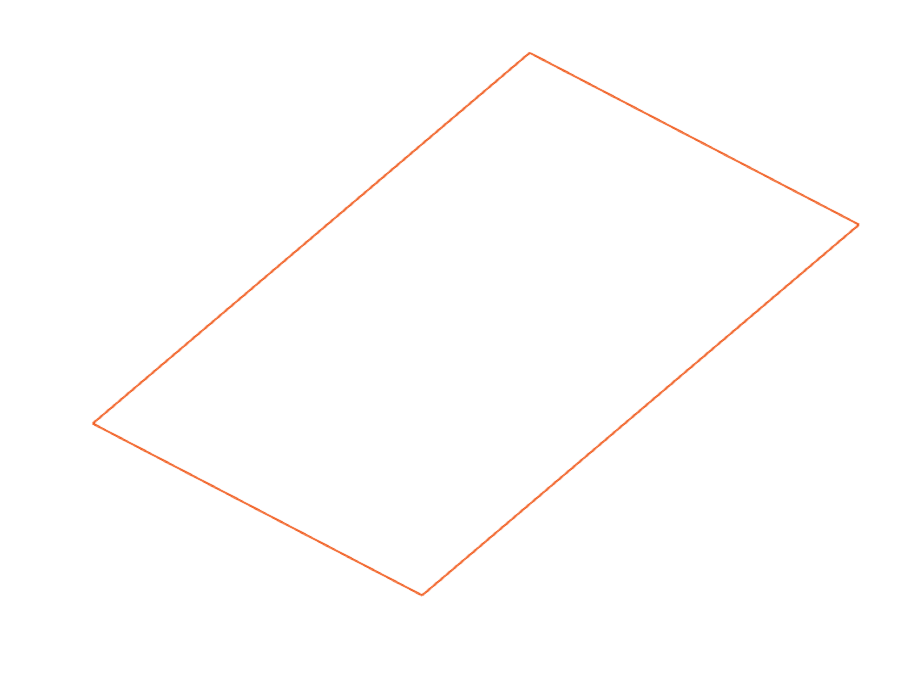
Buried conductor
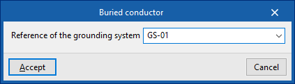
Inserts buried conductors from an IEC-type earthing system into the model. When adding this element, you must specify the system to which it belongs:
- Grounding system reference
IEC electrode
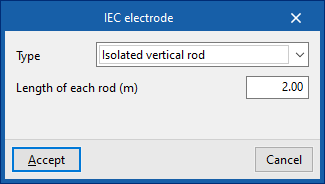
Inserts electrodes from an IEC-type earthing system into the model. When adding one of these elements, the following parameters must be specified:
- Type
The following IEC electrode types are available:- Single vertical rod / Two rods in a line / Three rods in a line / Three rods in a triangle / Four rods in a line / Four rods in square formation
The "Length of each rod" and the "Spacing between rods" are specified where applicable. - Buried vertical plate
Specify its "perimeter". - Steel column
Specify the "embedded length" and the "diameter of the circumscribed cylinder".
- Single vertical rod / Two rods in a line / Three rods in a line / Three rods in a triangle / Four rods in a line / Four rods in square formation
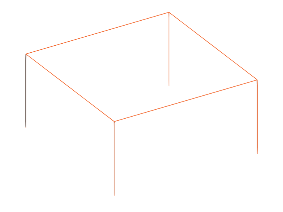
The IEC electrodes must be connected to a "buried conductor" to form an IEC grid.

Mesh IEEE
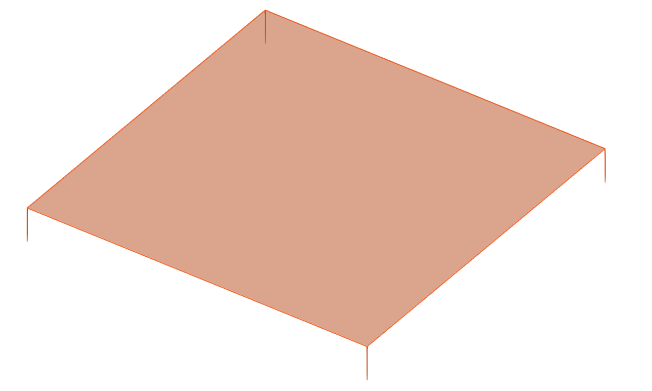
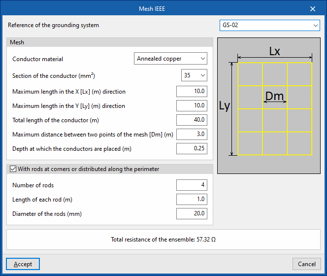
Inserts the mesh of an IEEE-type earthing system into the model. Clicking on this option opens a window displaying the following parameters:
- Reference of the grounding system
- Mesh
The parameters defining the mesh are as follows:- Conductor material (Annealed copper / Commercial copper / EC aluminium / 5005 aluminium / 6001 aluminium / 1020 steel / Stainless steel / 304 stainless steel / Zinc-coated steel / Copper-coated steel / Aluminium-coated steel)
- Section of the conductor (mm²)
- Maximum length in the X direction [Lx] (m)
- Maximum length in the Y direction [Ly] (m)
- Total length of the conductor (m)
- Maximum distance between two points of the mesh [Dm]
- Depth at which the conductors are placed (m)
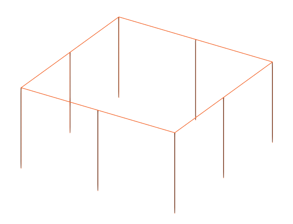
- With rods at the corners or distributed around the perimeter (optional) (in IEEE-type earthing systems using the "Complete, homogeneous soil" or "Complete, two-layer" analysis method)
- Number of rods
- Length of each rod (m)
- Diameter of the rods (m)
The program displays a diagram on the right to assist with the definition of these parameters.
At the bottom of the window, the "Total resistance of the ensemble" is displayed in ohms.
UNESA Mesh
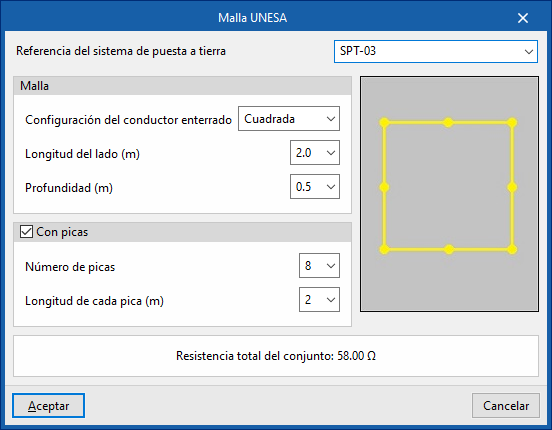
Inserts the mesh of a UNESA-type grounding system into the model. Clicking on this option opens a window displaying the following parameters:
- Earth reference
- Square mesh:
The parameters defining a square mesh are as follows:- Mesh
- Configuration of the buried conductor: Square
- Side length (m)
- Depth (m)
- With rods (optional)
- Number of rods
- Distance between each rod (m)
- Mesh
- Rectangular mesh:
The parameters that define a rectangular mesh are as follows:- Mesh
- Configuration of the buried conductor: Rectangular
- Dimensions (m)
- Depth (m)
- With rods (optional)
- Number of rods
- Distance between each rod (m)
- Mesh
- Longitudinal grid:
The parameters defining a longitudinal grid are as follows:- Mesh
- Configuration of the buried conductor: Longitudinal
- Depth (m)
- Rods
- Number of rods
- Length of each rod (m)
This value is determined by the selection of the previous parameters.
- Mesh
The program displays a diagram on the right to assist with defining the mesh.
At the bottom of the window, the "Total resistance of the ensemble" is displayed in ohms.
Grounding box
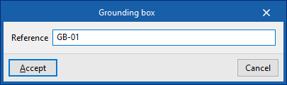
Inserts grounding boxes into the model. When adding this element, you must specify the following parameter:
- Reference