Defining types of receivers, grounding systems and protection levels
In the "Project" section of the main toolbar, you will find the options for defining the types of receivers, grounding systems and protection levels for the project:

Types of receiver
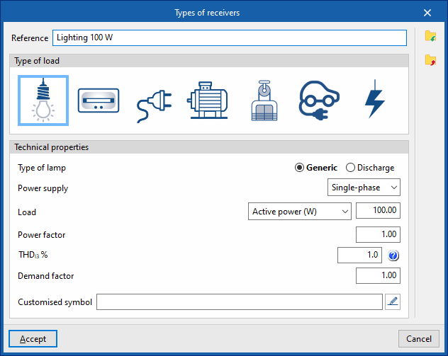
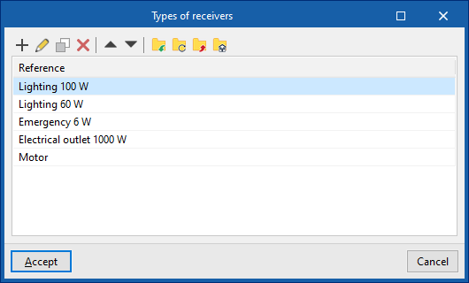
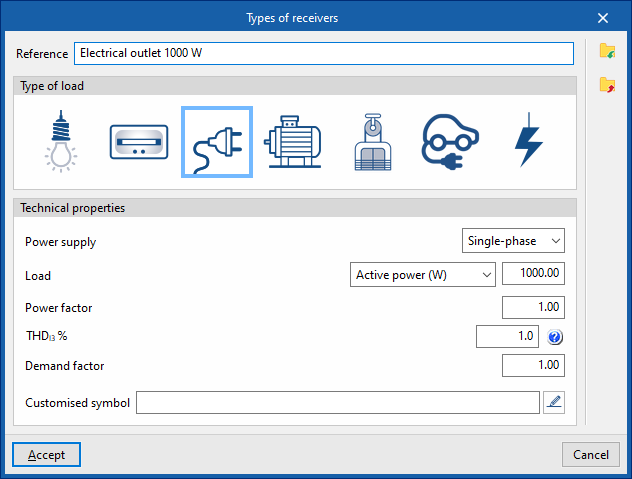
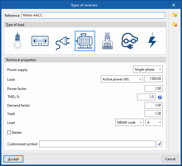
Provides access to a list of recipient types. In this list, you can create and edit recipient types by specifying the following parameters:
- Reference
Reference to the receiver type. - Type of load (Lighting / Emergency / Power socket / Motor / Lifting equipment / Electric vehicle charging / General)
- Technical properties
- Type of lamp (under "Lighting" and "Emergency")
- Generic / Downloadable
- Food
- Single-phase / Two-phase / Three-phase
- Load
- Active power (W) / Apparent power (VA)
- Demand factor
- THDI3 (%) (third-harmonic distortion index)
Allows you to enter the percentage of third-harmonic distortion present in the load. - Utilisation factor
- Performance (in "Engine" and "Lifting device")
- Start factor (for "Motor" and "Lifting device")
- NEMA code / Generic
- Starter (optional) (under "Motor" and "Lifting device")
- Direct drive / Variable frequency drive
- Customised symbol: Allows you to select a custom symbol from those previously created in "General options", "Symbols for drawings".
- Type of lamp (under "Lighting" and "Emergency")
The receiver types defined here can be loaded later by using the "Receivers" or "Assign" options in the main toolbar.
Grounding systems
This opens a window displaying a list of available grounding systems. These systems can be selected when entering the grounding components into the geometric model using the options in the "Grounding" section on the top toolbar.
The data for the various defined grounding systems can be exported to the BIM project and subsequently used in programs such as CYPELEC.
When designing a grounding system, the following parameters are specified:
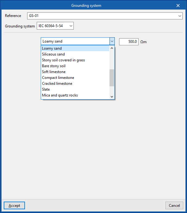
Definition of a grounding system IEC 60364-5-54
- Reference
- Grounding system: IEC 60364-5-54
- Type of terrain
- Soil resistivity (Ωm)
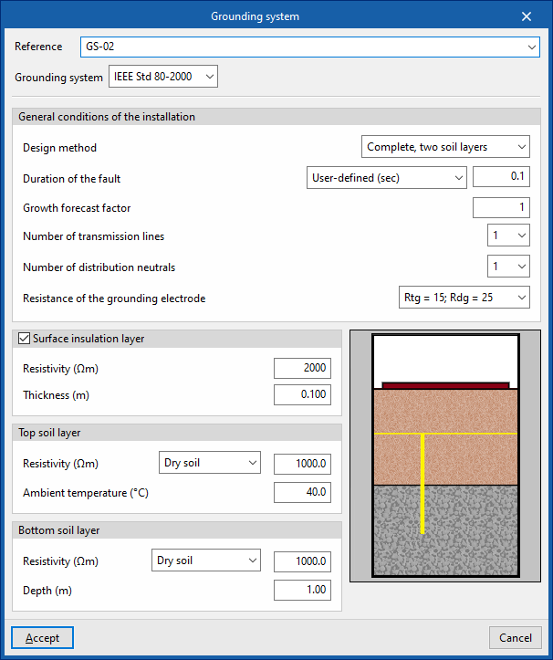
Definition of an grounding system – IEEE Std 80-2000
- Reference
- Grounding system: IEEE Std 80-2000
- General Terms and Conditions
- Design method (Simplified / Full, homogeneous ground / Full, two layers)
- Duration of the fault (User-defined / Provided by the protection mechanism)
- Growth forecast factor
- Number of transmission lines
- Number of distribution neutrals
- Resistance of the grounding electrode
- Surface insulation layer (optional)
- Resistivity (Ωm)
- Thickness (m)
- Top soil layer
- Resistivity (Ωm)
- Ambient temperature (°C)
- Bottom soil layer (in the "Complete, two soil layers" analysis method)
- Resistivity (Ωm)
- Ambient temperature (°C)
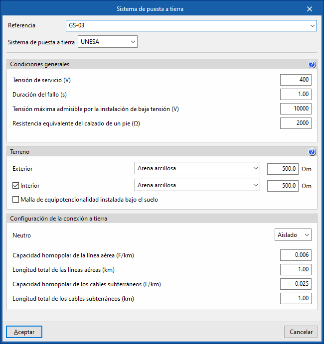
Definition of a UNESA grounding system
- Reference
- Grounding system: UNESA
- Terms and conditions
- Operating voltage (V)
- Duration of the fault (s)
- Maximum permissible voltage for the low-voltage installation (V)
- Equivalent resistance of footwear for one foot (Ω)
- Terrain
- Outdoor (Soil type, Soil resistivity)
- Indoor (optional) (Soil type, Soil resistivity)
- Equipotential bonding grid installed under the floor
- Grounding configuration
- Neutral: Isolated
- Homopolar capacitance of the overhead line (F/km)
- Total length of overhead lines (km)
- Homopolar capacitance of underground cables (F/km)
- Total length of underground cables (F/km)
- Neutral: To earth
- Resistance of the connection line to earth (Ω)
- Reactance of the feeder line to earth (Ω)
- Neutral: Isolated
Protected zone calculation
Sets the required level of protection for the external lightning protection system.
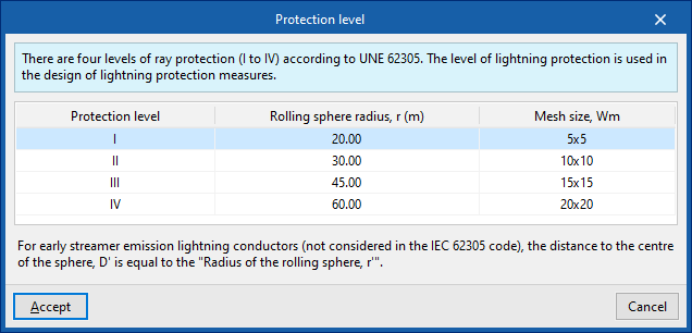
For installations with "Lightning and meshes", it is necessary to specify the "Rolling sphere radius, r" and the "Mesh size, Wm", which must not be exceeded by the dimensions of the meshes entered.
For installations with "Early streamer emission lightning conductor", the value for "Distance to the centre of the sphere, D" is required, as this enables the "Protected zone calculation". The diagram below shows the "Protected zone using an early streamer emission lightning conductor", as the sum of the cone and the sphere intersected by the indicated plane.
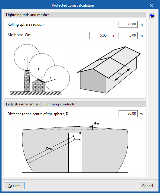
The wizard on the right allows you to import the data for the "Distance to the centre of the sphere, D", the "Rolling sphere radius, r" and the "Mesh size, Wm" based on one of the four levels of lightning protection (I to IV) defined in the UNE/IEC 62305 standard.