Examples of multiline diagrams for electrical installations
Below is an example of a multi-line diagram for an electrical installation that can be created in the program, showing the layout of the components and the options available for adding them to the model:
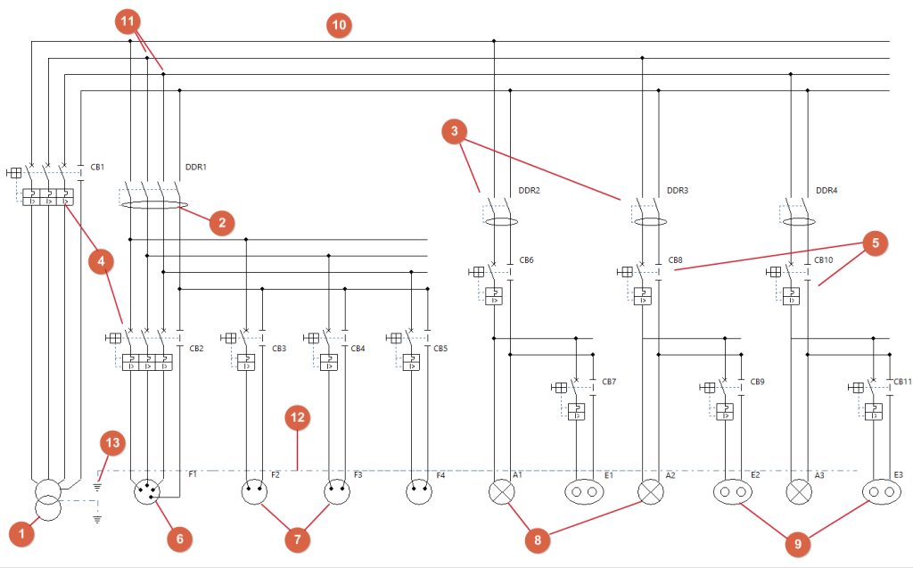
Multiline diagram of a system powered by a transformer
- Transformer (under "Power supply", "Transformer").
- 3P+N circuit breaker (from "Switchgear", "Residual-current device").
- 1P+N residual current devices (from "Switchgear", "Residual-current device").
- 3-pole plus neutral circuit breaker (from "Switchgear", "Circuit breaker").
- 1P+N circuit breakers (from "Switchgear", "Circuit breaker").
- 3P+N electrical outlet (from "Terminal elements", "Socket").
- 1P+N electrical outlet (under "Terminal elements", 'Sockets').
- 1P+N lighting (under "Terminal elements", "Lighting").
- 1P+N emergency lighting (under "Terminal elements", "Emergency").
- Bus route (under "Buses", "Bus route").
- Connection points (under "Buses", "Connection").
- Ground bus (from "Ground", "Earthing bus").
- Earth connection (from "Ground", "Ground").
All protective devices and other associated equipment for each line are shown in the relevant section according to their polarity.