Introduction
CYPELEC MULTILINE is a program that can be used to draw the multi-wire diagram of an electrical installation and print it on drawings in different formats.
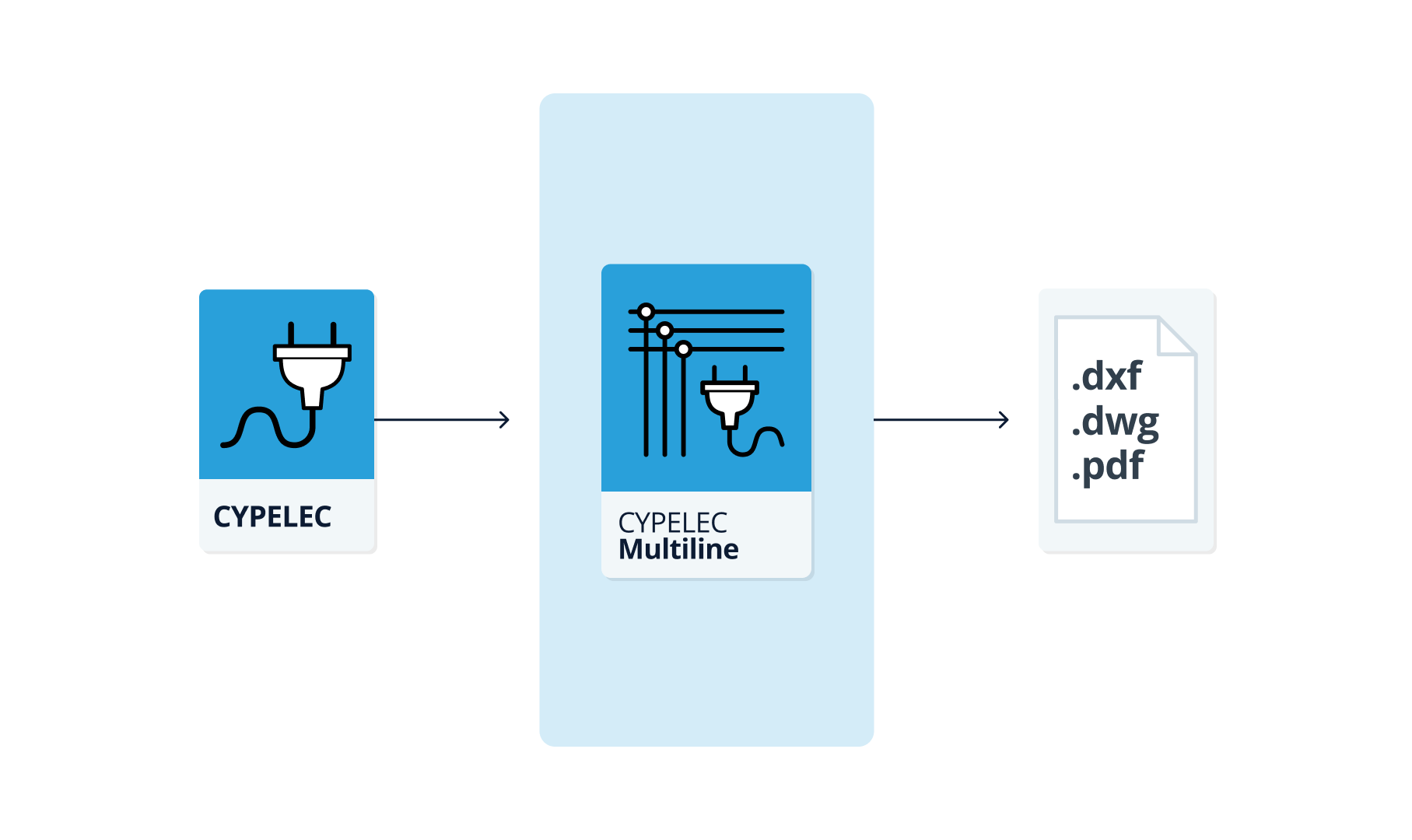
The application can automatically generate this diagram from the information provided by other low voltage electrical installation analysis tools, such as CYPELEC, which defines the single-line diagram and the connection between phases for each line, whether single-phase or three-phase.
The generated multi-wire diagram can be edited or the elements and the layout of the connection lines that make up the installation can be entered manually from scratch, including both the electrical conduits and the terminal elements and their corresponding protection switchgear. This representation is of great interest when transferring the preliminary design to the execution phase of the connections.
Workflows supported by the program
As an Open BIM tool connected to the BIMserver.center platform, CYPELEC MULTILINE offers a range of workflow options.
Data entry
Open design
- Free design of the multi-wire diagram by manually entering the components and drawing the connecting lines that make up the installation in CYPELEC MULTILINE.
Import and automatic generation
If you link the CYPELEC MULTILINE project to a BIM project on the BIMserver.center platform, you can perform the following actions:
- Importing data on low-voltage electrical installations designed in CYPELEC. This allows the multi-line diagram to be generated automatically from the data extracted from the BIM model. The model must contain the single-line diagram and the phase connection information for each line, whether single-phase or three-phase. Once the multi-line diagram has been generated, the user can modify it using the relevant tools without any restrictions.
| Note: |
|---|
| CYPELEC users must have selected the "Phased" configuration option and designed the installation in this mode before proceeding to export the IFC. |
Data output
- Exporting drawings to DXF, DWG and PDF formats.
- Exporting data generated using CYPELEC MULTILINE to the BIMserver.center platform. This allows authorised project participants to view the data.
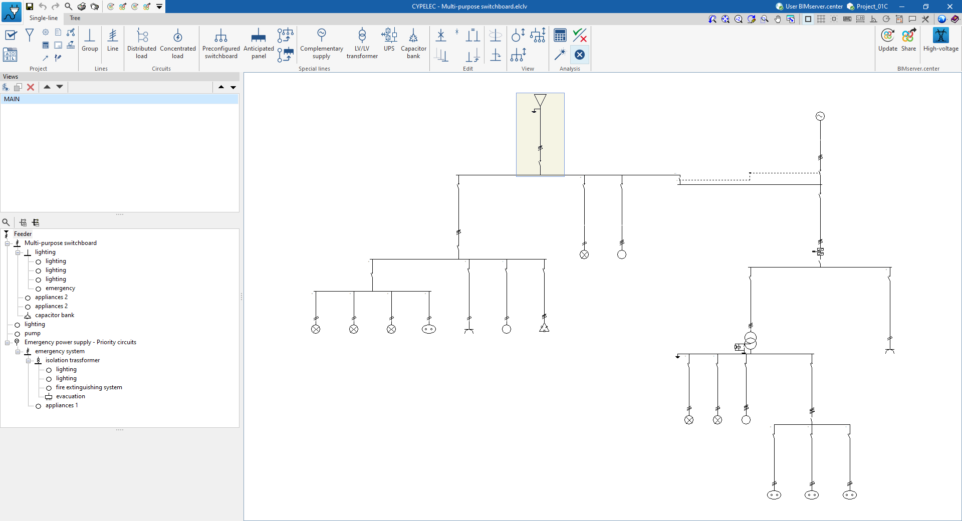
Work environment
The program has a simple work environment that helps to design the multi-line diagram quickly, entering and distributing the elements in different drawings in the desired formats.
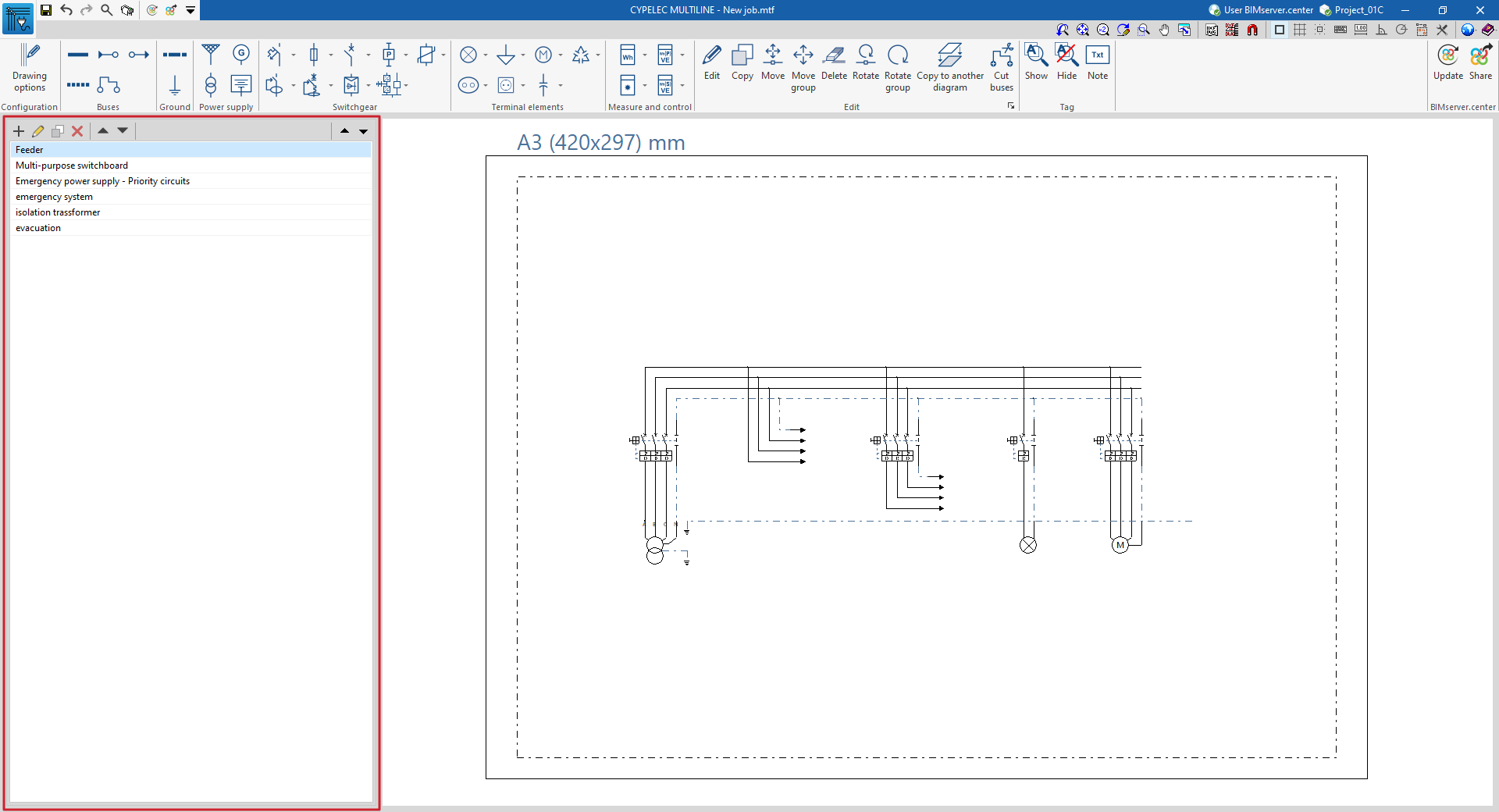
The interface displays the following:
- A top toolbar containing the tools for: configuring the drawing options; entering and editing the elements in the system, including buses, earthing elements, electrical switchgear, terminal elements and measurement and control elements; accessing the editing tools; and inserting annotations and labels.
- On the left-hand side panel, the tools for defining and navigating through the different drawings that make up the multi-wire diagram of the system.
- Finally, the work area, on the right of the screen, where the elements mentioned in the selected drawing are entered, edited and displayed.

Sequence of data input and output for drawing the multi-line diagram of an electrical installation
The multi-line diagram of an electrical installation can be defined in the program using the following sequence of data input and output:
- Creating a new project (from "File", "New").
- (Optional) Linking to BIMserver.center and importing BIM model data.
- Drawing options settings (under "Settings", "Drawing options").
- Inserting and/or reviewing the diagrams that make up the multi-line diagram using the options available in the left-hand side panel. These may have been generated from information extracted from the BIM model. A diagram layout will be established based on the panels, sub-panels and special elements of the installation entered into the original program.
- Inserting and/or reviewing the elements and the routing of the connection lines that make up the installation (from the options in the "Buses", "Earth", "Power supply", "Switchgear", "Terminal elements" and "Measure and control" blocks) on each drawing in the workspace. These may have been generated from information read from the BIM model.
- Printing drawings (from "File", "Drawings").
- Exporting to BIMserver.center (from "BIMserver.center", "Share").
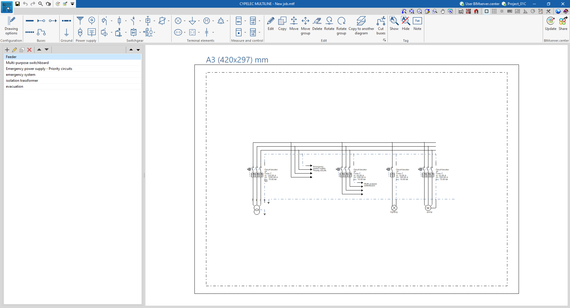
Examples of multiline diagrams for electrical installations
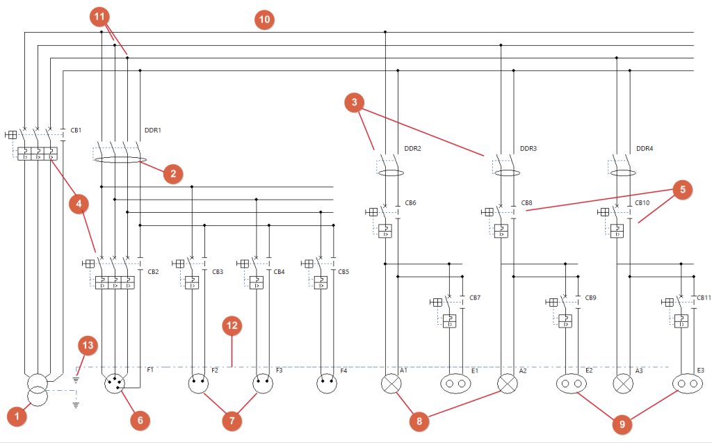
Below is an example of a multi-line diagram for an electrical installation that can be created in the program, showing the layout of the components and the options available for adding them to the model:
Multiline diagram of a system powered by a transformer
- Transformer (under "Power supply", "Transformer").
- 3P+N circuit breaker (from "Switchgear", "Residual-current device").
- 1P+N residual current devices (from "Switchgear", "Residual-current device").
- 3-pole plus neutral circuit breaker (from "Switchgear", "Circuit breaker").
- 1P+N circuit breakers (from "Switchgear", "Circuit breaker").
- 3P+N electrical outlet (from "Terminal elements", "Socket").
- 1P+N electrical outlet (under "Terminal elements", 'Sockets').
- 1P+N lighting (under "Terminal elements", "Lighting").
- 1P+N emergency lighting (under "Terminal elements", "Emergency").
- Bus route (under "Buses", "Bus route").
- Connection points (under "Buses", "Connection").
- Ground bus (from "Ground", "Earthing bus").
- Earth connection (from "Ground", "Ground").
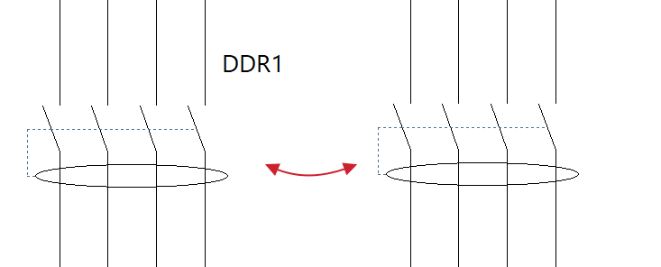
All protective devices and other associated equipment for each line are shown in the relevant section according to their polarity.
Creating a new job, linking to a project and importing data
When you launch the app and click on "New", you are given the option to create a "New job". After entering the "File name" and "Description", the project can then be added to an existing project on BIMserver.center.
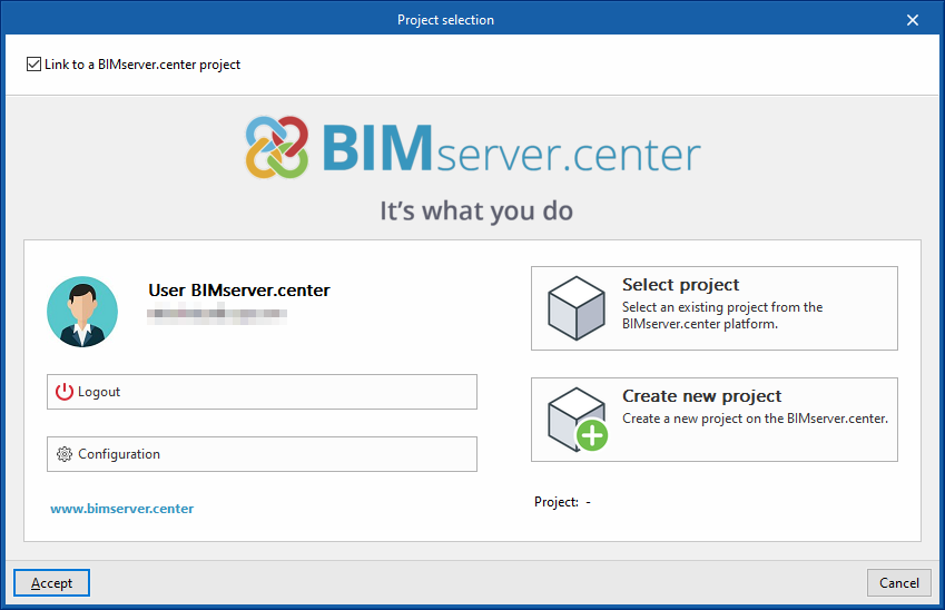
This is done in the "Project selection" window, which offers the following options:
- On the left-hand side, you can sign in using a BIMserver.center account.
- On the right-hand side, you will find the "Project selection" option to choose an existing project. You also have the option to "Create a new project". In that case, the project you create will be visible on BIMserver.center from that point onwards.
- You have the option to start the project without linking to the BIMserver.center platform. To do this, simply uncheck the box labelled "Link to a BIMserver.center project", which is located in the top-left corner.
Once the new project has been created, you will be taken to the program’s main interface. At any point thereafter, whilst working on the project, you can share or import project files via the "BIMserver.center" panel, located in the top-right-hand corner of the main interface.

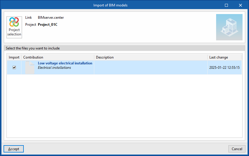
Importing BIM models
When creating a new project, if you have selected a project hosted on the BIMserver.center platform via "Select project", the "Import BIM models" window will appear, displaying the files contained in that project in IFC format.
To include the information from a specific project file, tick the "Import" box and confirm.
Import results
The program will generate the diagrams that make up the multi-line diagram based on the layout of the main switchboards, sub-switchboards and special components of the installation, as derived from the BIM model, provided that this information is included.
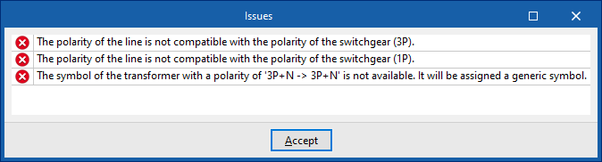
In addition, a window appears showing any "Issues" that occurred during the data import process and the actions taken by the program to resolve them, where possible.
Creating and editing drawings
On the left-hand side, the program displays a list of the various plans that make up the installation’s multi-line diagram. The main workspace, on the right, will display the drawings selected from this list.
The toolbar at the top of this section displays the following options:
- New
Creates a new plan. - Edit
Edits the selected plan. - Duplicate
Creates a copy of the selected plan. - Delete
Deletes the selected layer. - Move (up/down)
Reorders the layers in the list. - Go to the previous level / Go to the next level
Select the previous or next level from the list.
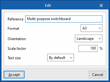
When creating or editing a drawing, you need to define the following parameters:
- Reference
Drawing reference. - Format
Selects the format of the plan from those available. - Orientation (Vertical / Horizontal)
Defines the orientation of the plane. - Scale factor (%)
Defines the scale factor of the plan. - Text size (Default / Other)
Set the text size.
Configuring drawing options
In the "Configuration" section of the main toolbar, you will find the "Drawing options":

Drawing options
These options allow you to configure the display of the following elements in the diagram, as well as the font size of their label text:
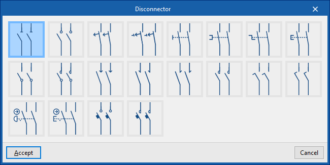
- Disconnectors
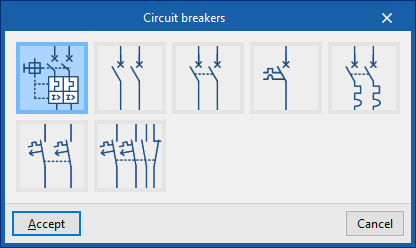
- Circuit breakers
- Fuse carrier
- Differential switch
- Magnetic starter
- Contactors
- Switch
- IGM (Main switch)
- Arrows
- Motors
- Motor starters
- Texts
- Height

By clicking on each element category, you can select the symbol used to represent it from those available in the program, which are taken from various standards.
Tools for inserting elements into the multi-line diagram
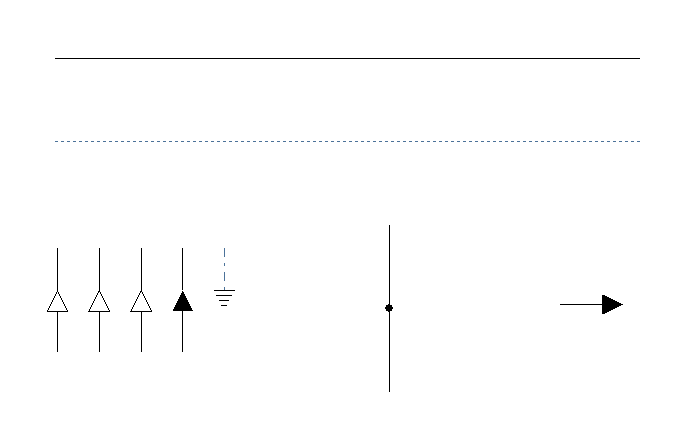
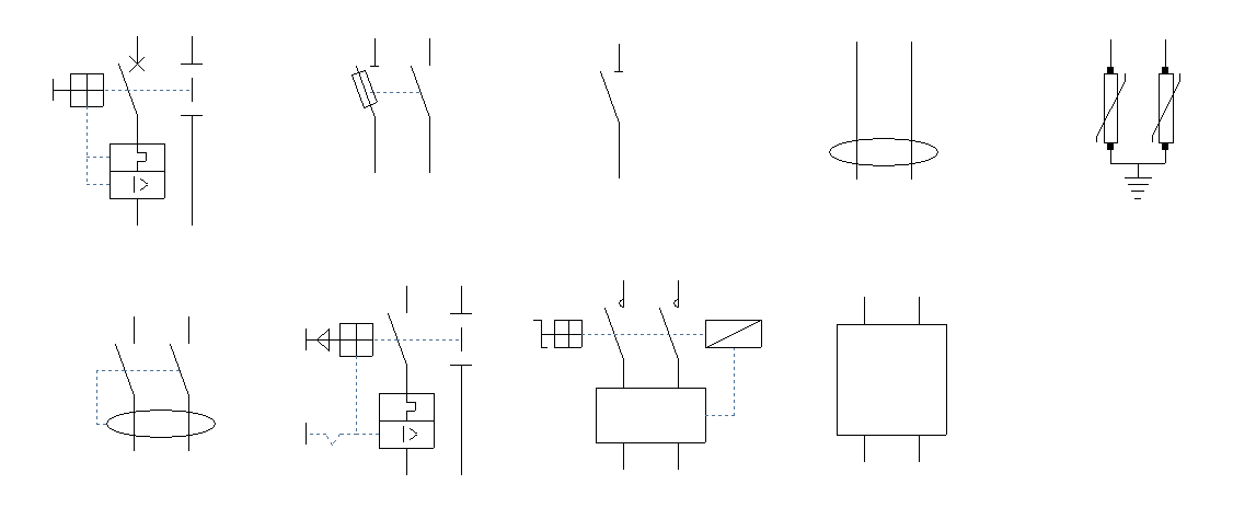
The "Buses", "Ground", "Power supply", "Switchgear", "Terminal elements" and "Measurement and control" sections of the main toolbar contain the options for inserting and positioning the various components of the multiline diagram within each of the defined views:

Options in the "Buses" section
This section contains the following options:
- Bus line
Draws bus lines connecting the elements in the diagram. - Interlock
Inserts an interlock line. - Continuation points
Inserts continuation points between sections of a diagram. For example, a power distribution board diagram may include a continuation point that leads to a sub-board. The sub-board diagram can then start from a continuation point. The following data must be defined:- Type (1BR / 1BR+1BTH / 2BR / 2BR+2BTH / 2BR+2BTH / 2BR+2BTH / 3BR / 3BR+3BTH / 3BR+3BTH / 3BR+3BTH / 4BR)
- Description
- Connection
Connection points to be added to a bus or interlock line. - End points
Inserts end points for the diagrams. The following information must be defined:- Description
Options in the "Earth" section
This section contains the following options:
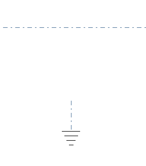
- Earthing bus
Inserts a ground bus line. - Earth
Specify a ground connection point.
Options in the "Power" section
This section contains the following options:
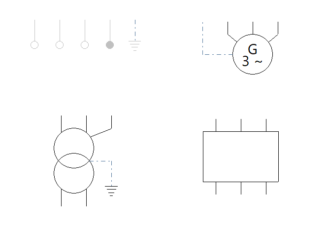
- Supply
Inserts a supply point. The following details must be provided:- Type (2P / 3P / 4P / 1PN / 2PN / 3PN / 2PT / 3PT / 1PNT / 2PNT / 3PNT)
- Description
- Transformer
Inserts a transformer. You must specify the following details:- Earthing diagram (TT (neutral to earth) / TN-S (neutral earthed) / IT (isolated neutral) / IT (impedance-coupled neutral))
- Input (Supply / 3-pin / 1-pin + neutral / 3-pin + neutral)
- Output (3-pin / 1-pin + N / 3-pin + N)
- Description
- Generator
Inserts a generator. You must specify the following details:- Type (2PT / 3PT / 4PT)
- Description
- Battery
Inserts a battery. You must specify the following details:- Type (1-bedroom / 2-bedroom / 3-bedroom / 3-bedroom / 4-bedroom)
- Description
Options in the "Switchgear" section
This section contains the following options:
- Circuit breaker (1P / 1PN / 2P / 3P / 3PN / 4P)
Inserts a circuit breaker. The following parameter must be specified:- With surge protector for permanent overvoltages (optional)
- Residual-current device (1P / 1PN / 2P / 3P / 3PN / 4P)
Inserts a residual current circuit breaker. - Fuse (1P / 1PN / 2P / 3P / 3PN / 4P)
Inserts a fuse. - Magnetic starter (1P / 1PN / 2P / 3P / 3PN / 4P)
Inserts a magnetic starter. - Sectionaliser (1P / 1PN / 2P / 3P / 3PN / 4P)
Inserts a sectionaliser. - Starter (1-pole / 2-pole / 3-pole / 3-pole / 4-pole)
Inserts a starter. - Power control system (1P / 2P / 3P / 3PN / 4P)
Inserts a power control system. - UPS (1-phase / 2-phase / 3-phase / 3-phase / 4-phase)
Inserts an uninterruptible power supply. - Surge protector for transient overvoltages (1PN / 2P / 3P / 3PN / 4P)
Inserts a surge protector for transient overvoltages.
You can enter a "Description" for each of these items.
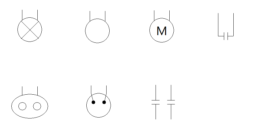
Options in the "Terminal elements" section
This section contains the following options:
- Lighting (1-point / 2-point / 3-point / 3-point / 4-point)
Inserts a light fitting. You must specify the following parameter:- Protection (optional)
- Emergency (1-light / 2-light / 3-light / 3-light / 4-light)
Inserts an emergency light fitting. You must specify the following parameter:- Protection (optional)
- Generic (1BR / 2BR / 3BR / 3BR / 4BR)
Inserts a generic outlet. You must specify the following parameter:- Protection (optional)
- Electrical outlet (1PN / 2P / 3P / 3PN / 4P)
Inserts an electrical outlet. You must specify the following parameter:- Protection (optional)
- Motor (1PN / 2P / 3P / 3PN / 4P)
Inserts a motor. You must specify the following parameter:- Protection (optional)
- Capacitor (1P / 1PN / 2P / 3P / 3PN / 4P)
Inserts a capacitor. - Capacitor bank (1PN / 2P / 3P / 3PN / 4P)
Inserts a capacitor bank.
You can enter a "Description" for each of these elements.
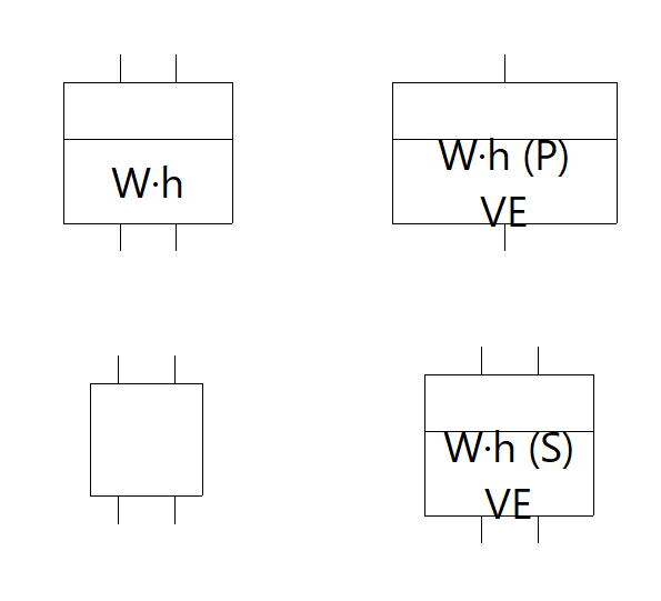
Options in the "Measurement and control" section
This section contains the following options:
- Meter (1B / 1BR / 2B / 3B / 3BR / 4B)
Inserts a meter. - Network analyser (1-phase / 2-phase / 3-phase / 3-phase neutral / 4-phase)
Inserts a network analyser. - Main electricity meter (EV) (1P / 1PN / 2P / 3P / 3PN / 4P)
Inserts a main electricity meter in premises equipped with infrastructure for charging electric vehicles. - Secondary electricity meter (EV) (1P / 1PN / 2P / 3P / 3PN / 4P)
Inserts a secondary electricity meter in facilities equipped with infrastructure for charging electric vehicles.
You can enter a "Description" for all elements.
Editing tools
The "Edit" section of the main toolbar contains the tools for editing the elements of the diagram:

The available options are as follows:
| Edit | Edits the parametric properties of the selected element in the model. | |
| Copy | Creates a copy of one or more elements. | |
| Move | Moves an element or a node within an element. | |
| Move group | Moves a group of elements. | |
| Delete | Deletes a previously entered element. | |
| Rotate | Rotates an element in plan view. | |
| Rotate group | Rotates a set of elements about the centre, with the angle of rotation defined by two points. | |
| Copy to another diagram | Creates a copy of the selected elements on other plans or layouts. After selecting the elements to be copied, tick the boxes for the layouts to which you want the elements to be copied. | |
| Cut buses | Splits a bus line, an interlock or a ground bus at the selected point. |
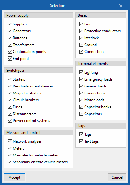
In addition, the button at the bottom right of the "Edit" panel opens the "Selection" window, where you can select or deselect the categories and/or tags you wish to edit.
Tag management
In the "Tag" section of the main toolbar, you will find options for inserting notes on the diagrams and managing the visibility of element tags:

Show
Displays the tag for the selected elements. To change the text displayed in the tag, you must edit the element using the "Edit" option in the "Edit" section and modify the "Description" field.
Hide
Hides the tags of the selected elements.
Note
Inserts a tag onto the drawing with text entered by the user. You can place the text inside a box:
- With a box (optional)

Results output
Drawings in DWG, DXF or PDF format
The program can print the job drawings on any graphic peripheral configured on the computer or create DWG, DXF or PDF files.
The drawing edition configures the "Reference" of the drawing and to activate or deactivate the representation of each of the categories of elements in the installation, as well as the tags entered as annotations.
The drawings can be obtained via the "Drawings" option at the top of the interface or via the "Drawings" option in the "File" menu.


Integration into the BIMserver.center platform
Many of CYPE's programs are connected to the BIMserver.center platform and allow collaborative work to be carried out via the exchange of files in formats based on open standards.
Please note that, to work on BIMserver.center, users can register on the platform free of charge and create a profile.
When accessing a program connected to the platform, the program connects to a project in BIMserver.center. This way, the files of the projects that have been developed collaboratively in BIMserver.center are kept up to date.

| More information: |
|---|
| For further details related to using CYPE software via the BIMserver.center platform, please click on this link. |
Options available on CYPELEC Multiline
The "BIMserver.center" section of the main toolbar contains the features needed to use the program alongside other BIMserver.center tools:

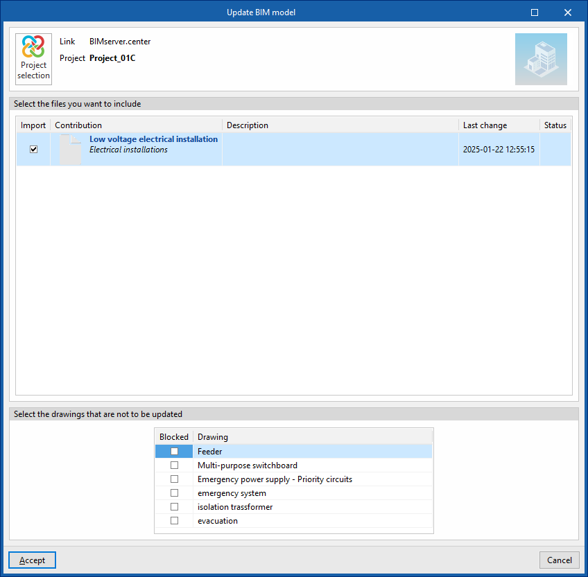
Updating
Update the information contained in the files previously imported into the project, or import new files if required.
To do this, at the top you must "Select the files you want to include".
At the bottom, you can "Select the drawings you do not want to update" by ticking the relevant boxes in the list.
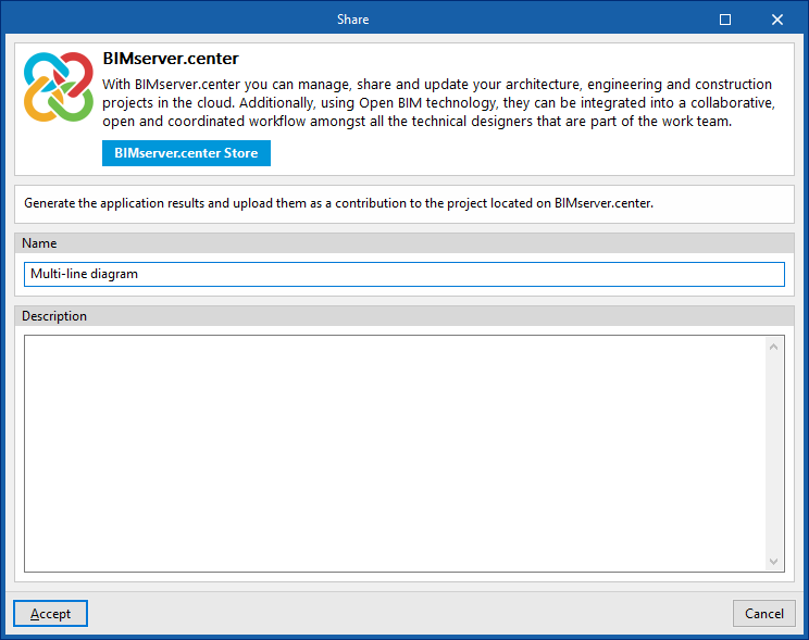
Sharing
Export the installation data generated by the program to BIMserver.center so that you can share it with other users.
During the export process, you can specify the details relating to the IFC file to be exported:
- Name
- Description