
Project requirements and generating single-line diagrams
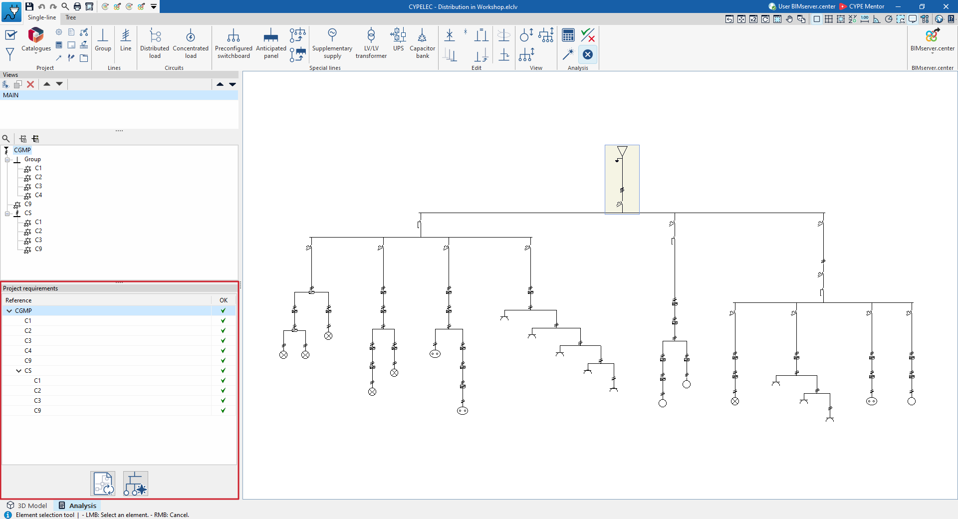
If the load distribution and circuits have been developed in the "3D Model" tab, it is possible to import the information into the "Calculation" tab. In this case, the specific "Project requirements" panel on the left-hand side of the interface is used, both in the "Single-line" tab and the ‘Tree’ tab, which provides additional functionality.
This section contains two buttons:
 The first button, "View the electrical layout shown on the "3D Model" tab and keep the information up to date", is the only one displayed if no previous reading has been taken. Clicking it performs or updates this reading of the information from the modelling tab, and the "Project requirements" panel is generated and displayed.
 The second button: "Generate the single-line diagram from the latest update". Using this tool, the program can automatically generate a single-line diagram from scratch based on the latest information read from the "3D Model" (the lines and all circuits are defined and connected in accordance with the diagram read from the "3D Model" tab), which meets the project’s requirements. During this process, the existing single-line diagram is deleted and regenerated; therefore, any changes made using the tools on the "Analysis" tab (such as the addition of new lines or loads not drawn on the "3D Model" tab) will be lost.
 The first button, "View the electrical layout shown on the "3D Model" tab and keep the information up to date", is the only one displayed if no previous reading has been taken. Clicking it performs or updates this reading of the information from the modelling tab, and the "Project requirements" panel is generated and displayed.
 The second button: "Generate the single-line diagram from the latest update". Using this tool, the program can automatically generate a single-line diagram from scratch based on the latest information read from the "3D Model" (the lines and all circuits are defined and connected in accordance with the diagram read from the "3D Model" tab), which meets the project’s requirements. During this process, the existing single-line diagram is deleted and regenerated; therefore, any changes made using the tools on the "Analysis" tab (such as the addition of new lines or loads not drawn on the "3D Model" tab) will be lost.
The "Project requirements" panel shows the reference number for each of the lines or circuits identified in the "3D Model" tab, along with a marker indicating whether or not each one meets the requirements set out in the diagram developed in the "Analysis" tab.
Double-clicking on each requirement opens a window showing details of that requirement.
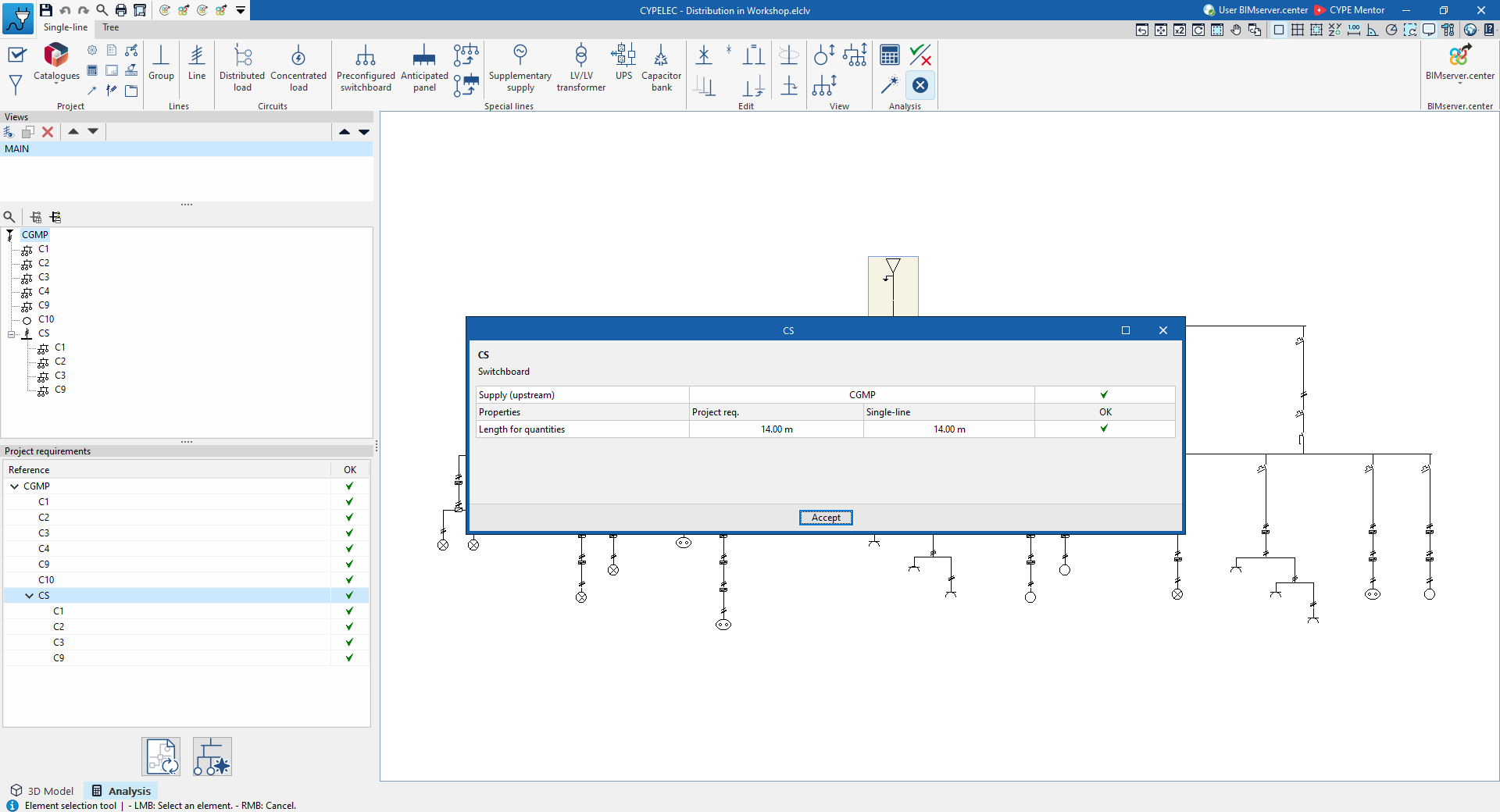
Compliance with the project requirements for each of the lines and circuits is based on checking the following points against the information displayed on the "3D Model" tab and the information on the "Analysis" tab (which can be edited using the tools on this tab):
- On lines forming part of interconnection installations and feeder lines to switchboards or sub-switchboards, the specified measurement length must be adhered to.
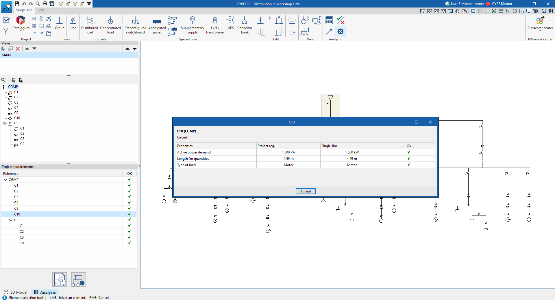
- In the case of circuits belonging to switchboards, and where circuits with concentrated loads are involved (which the program generates when loads are entered in the "3D Model" tab and assigned to switchboards, but without routing the connection conduits), the total active power demand of the circuit and the measurement length must be taken into account.
- In the case of circuits belonging to switchboards, and where circuits have a distributed load (which the program generates when loads are entered in the "3D Model" tab and assigned to switchboards, and once the connection routes have been drawn), in addition to the active power demand and the measurement length, the definition and distribution of each load along its supply circuit must be correct, and the electrical characteristics of each load must be correct.
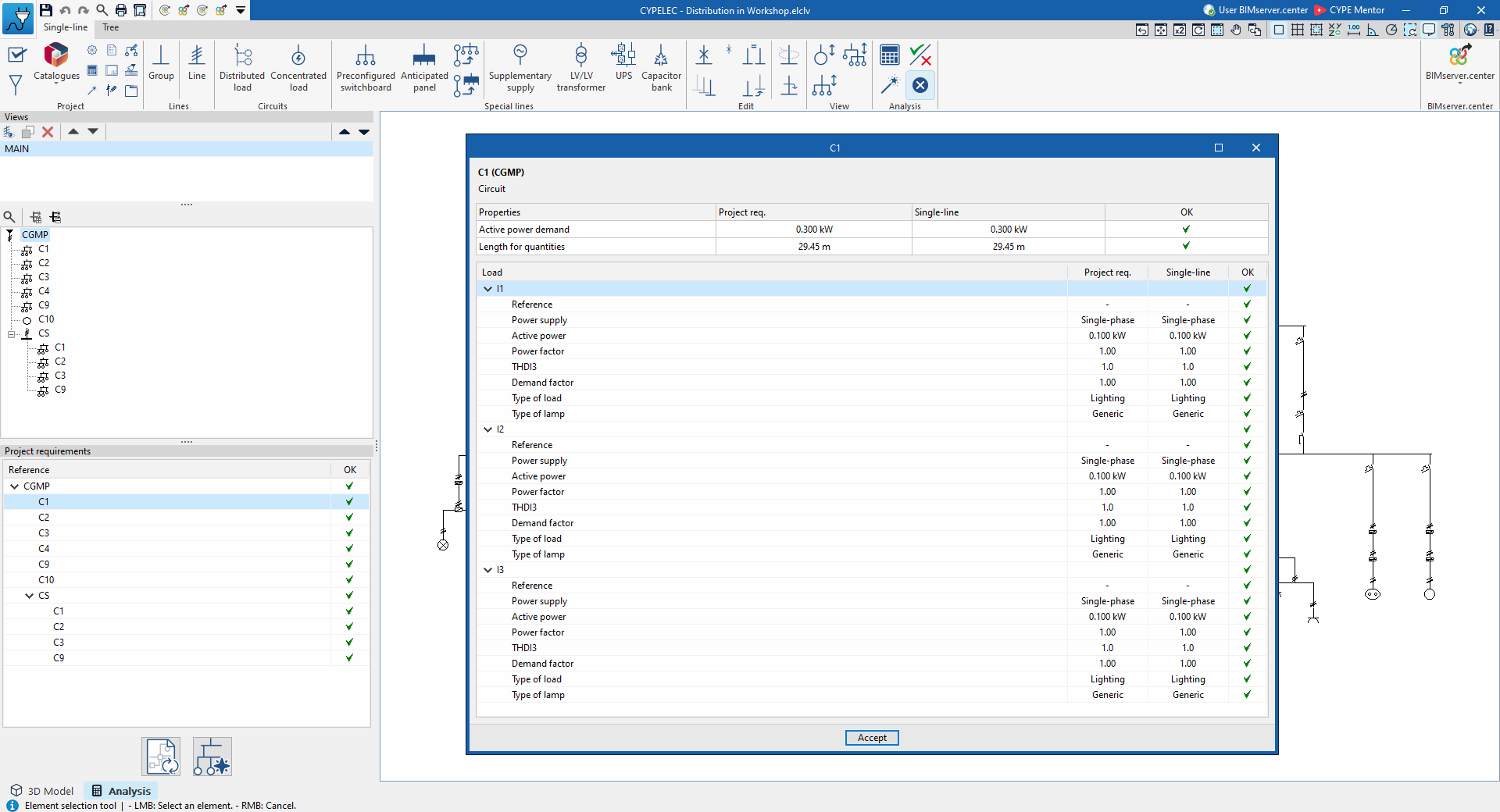
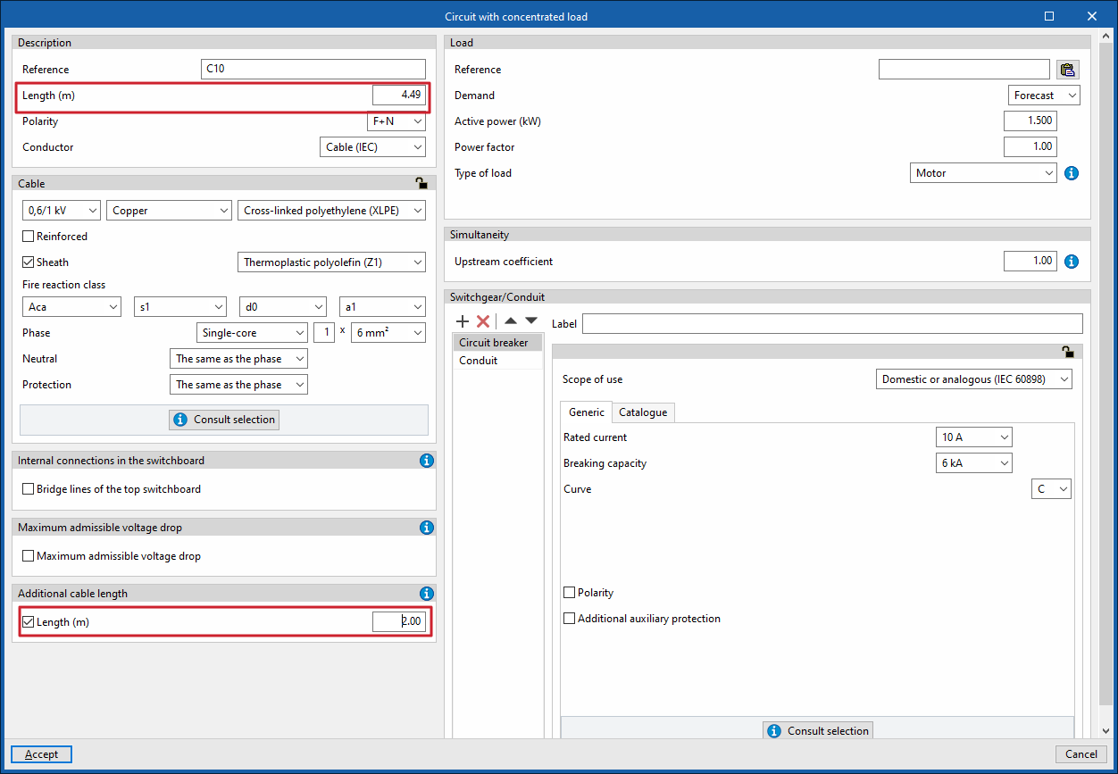
It is worth noting that, in order to meet the requirement for a circuit’s measurement length, the sum of the calculated length and the sum of the additional lengths must be equal to or greater than the required length. Both lengths are displayed in a circuit’s editing panel, as shown in the image on the right.