
Results output
Checking results on screen ("Single-line" tab)
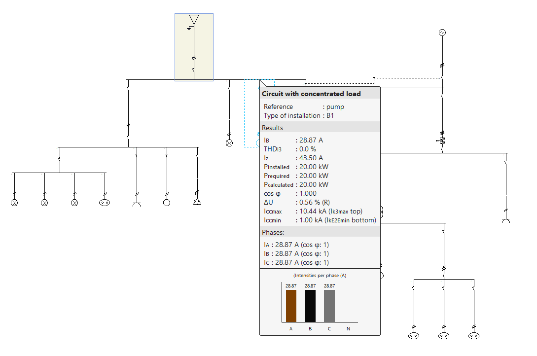
After carrying out the analysis, the program displays the analysed results and magnitudes on the screen by means of a drop-down tooltip that appears when the cursor hovers over an element of the system.
Details on the elements in the single-line diagram represented on the screen can also be displayed in the same way as in the drawing representation.
If the "Show the same details as on the drawing" option is activated, these details can be configured from "Single-line diagram drawings" and also in the "Project" group of the general interface.
Reports by element ("Single-line" tab)
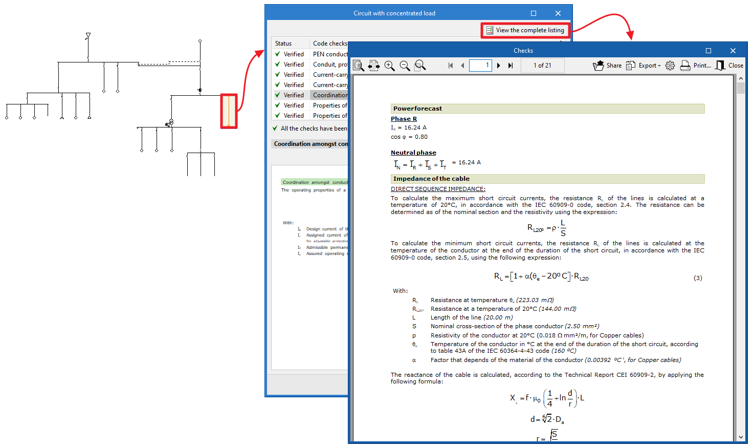
In the "Single-line" tab, by clicking on each element, the program can be used to consult the analysis reports and the detailed checks carried out on the element.
Each of the checks and the complete list of reports can be printed directly, or HTML, PDF, TXT, RTF or DOCX files can be generated with their contents.
VViewing checks ("Tree" tab)
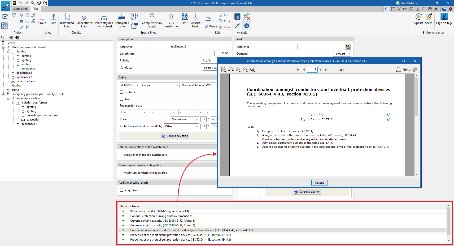
The "Tree" tab includes a panel for viewing the checks carried out on each line.
To access the corresponding check report, click on the "Consult checks" option or double-click on the check to be displayed with the left mouse button.
Job reports
The program can also print the following job reports with the printer or generate HTML, PDF, TXT, RTF or DOCX files:
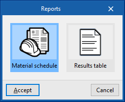
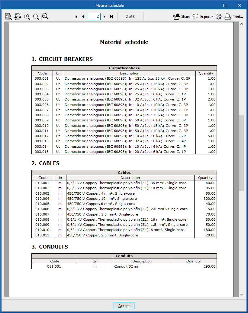
- Material schedule
Displays a report with the material schedule used in the system. The data on circuit breakers, fuses, magnetic starter, starters, differential switches, cables, conduits and other elements in the installation (such as meters or junction boxes) are organised in a series of tables that include the following information:- Code
- Unit
- Description
- Quantity
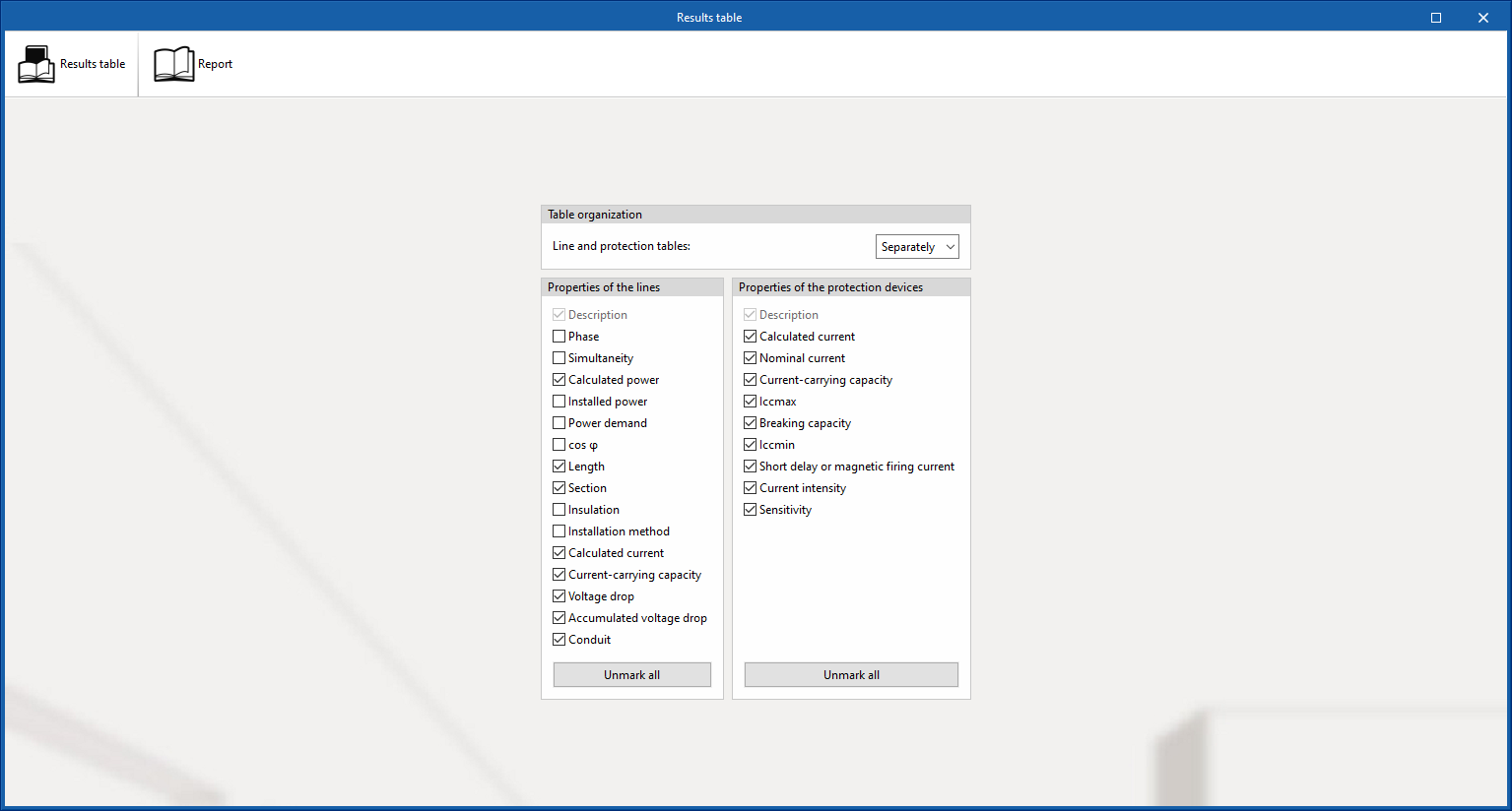
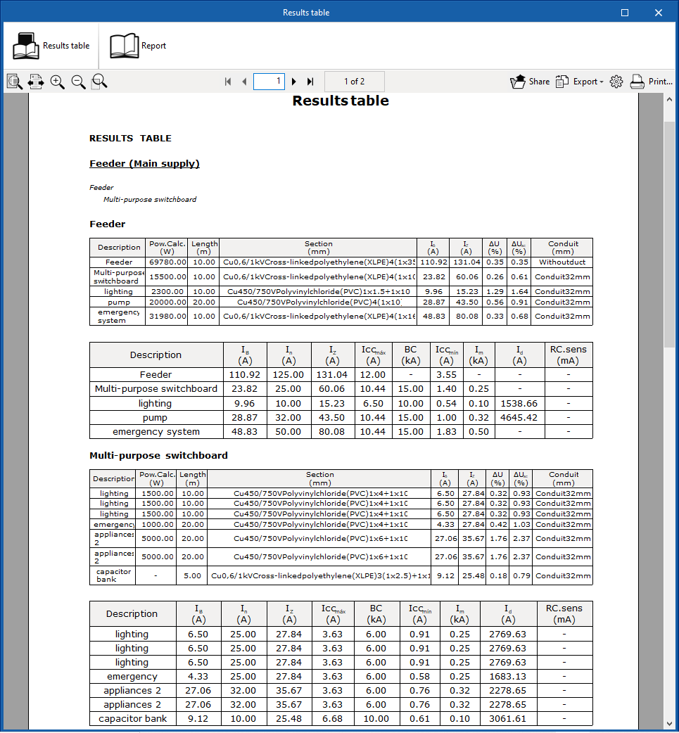
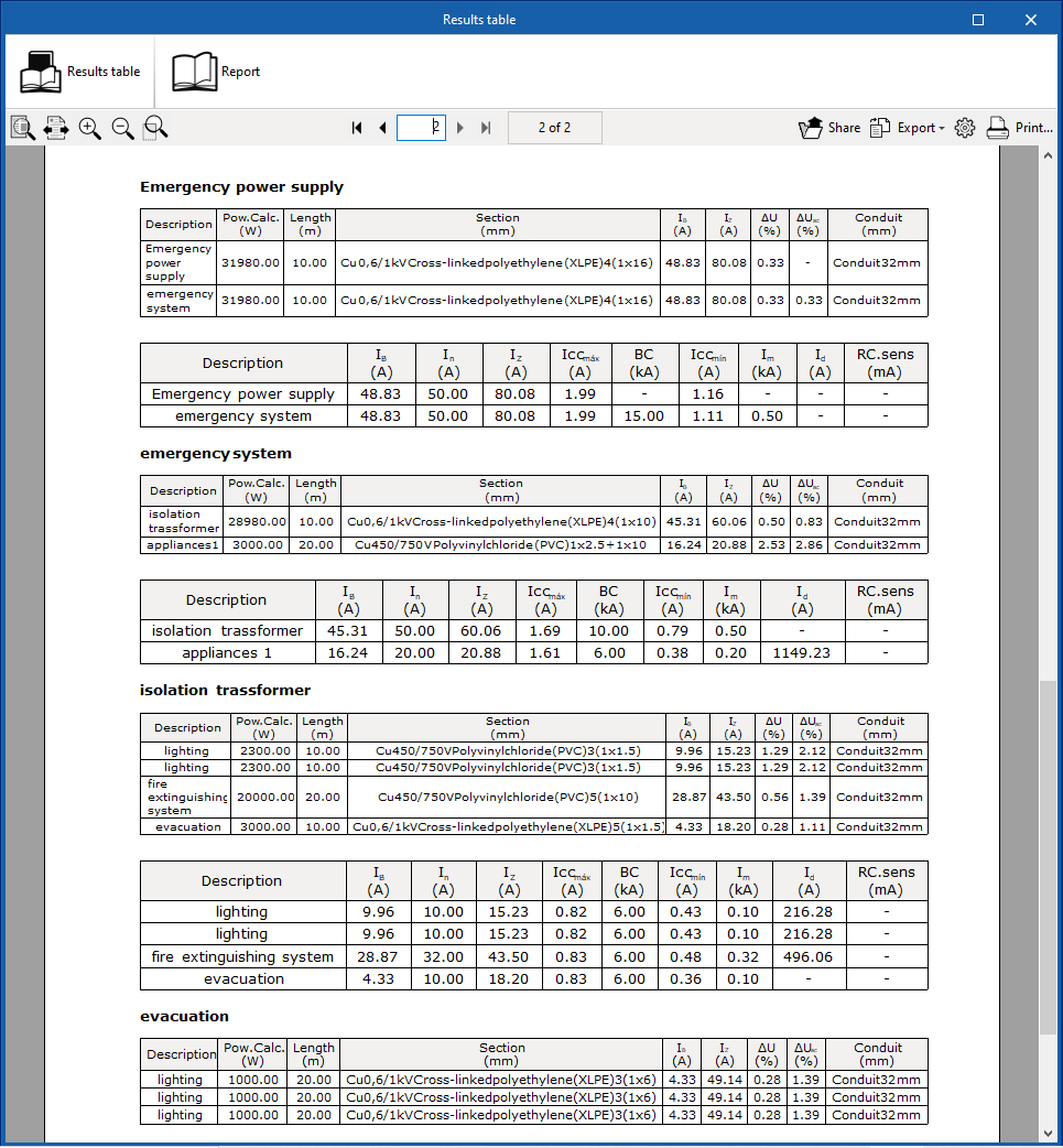
- Results table
Displays a report with the results of the system's analysis. This report includes the most relevant information for each of the lines as well as the results of the checks carried out, allowing users to decide which data appears in the tables and which does not. The program allows the following information to be configured:- Sorting line and protection tables (Joint / Separately)
The option of displaying line and protection information together or separately allows the selected data to be broken down into separate tables so that the tables fit the paper dimensions more conveniently and the visibility of the data they contain is improved. - Properties of the lines
Allows users to check or uncheck the displayed information related to the lines:- Description
- Phase
- Simultaneity
- Power (Calculated power, Installed power, Power demand)
- Power factor (cos φ)
- Length
- Section
- Insulation
- Installation method
- Intensity (Calculated current, Allowable current)
- Voltage drops (Voltage drop, Accumulated voltage drop)
- Conduit
- Properties of the protection devices
Allows users to check or uncheck the displayed information related to the protections:- Description
- Calculated current
- Nominal current
- Current-carrying capacity
- Maximum short circuit current (Iccmáx)
- Breaking capacity
- Short delay or magnetic firing current
- Current intensity
- Sensitivity
- Sorting line and protection tables (Joint / Separately)
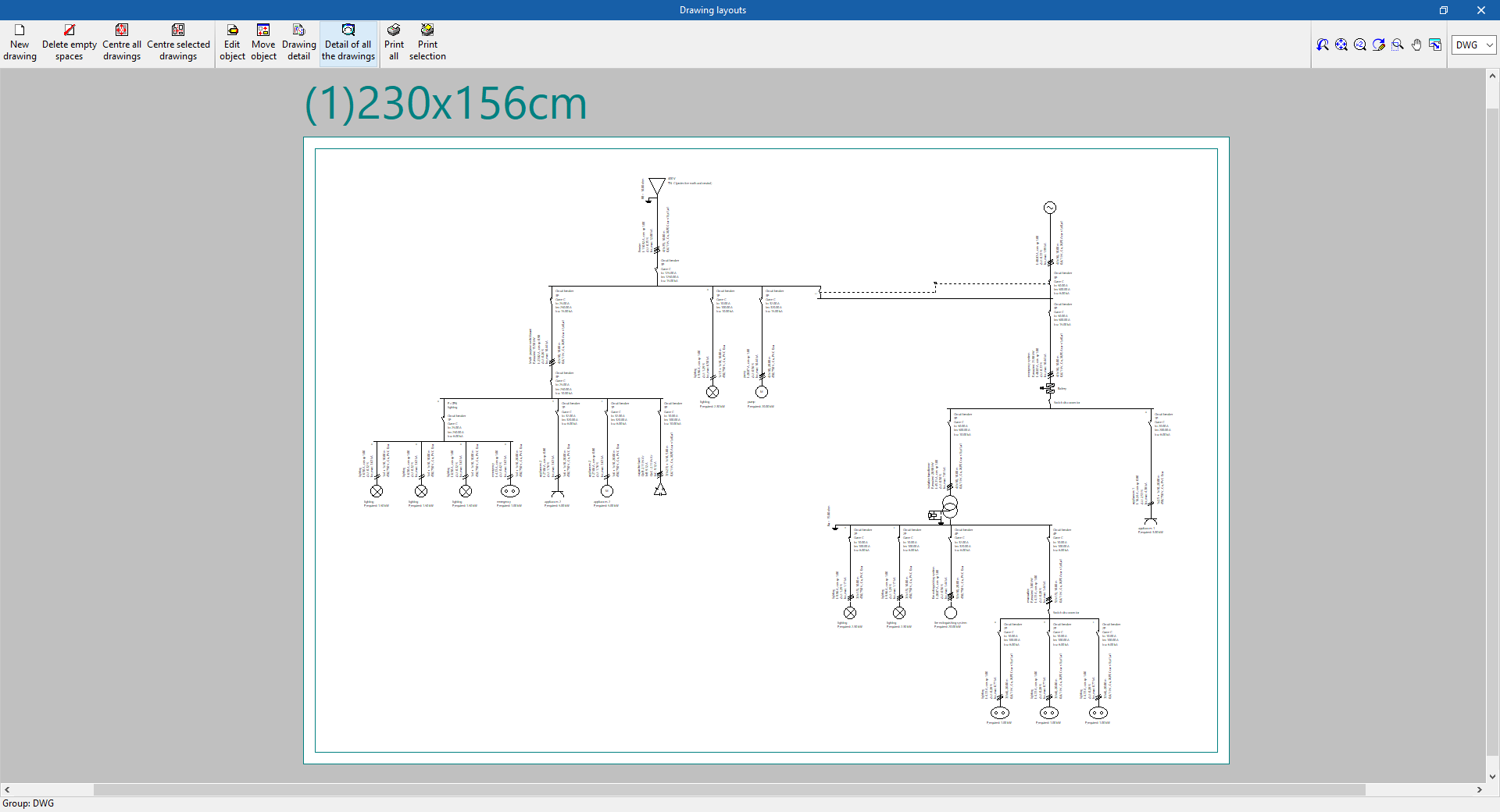
Drawings of the single-line diagram in DWG, DXF or PDF format
This allows users to print the job drawings of the single-line diagram on any graphic peripheral that is configured on the computer, or to create DWG, DXF or PDF files.
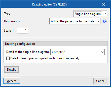
The following options can be configured when editing the drawing:
- Type
- Dimensions
- Adjust the paper size to the scale
This way, through the scale, the desired size for the diagram can be selected, and the paper dimensions will be automatically adjusted for the layout. - Adjust the scale to the paper size
This way, the desired print format can be defined in order to frame the diagram in the formats supported by the printer. The program optimises the management of the free spaces in the diagram plan to allow a larger size in the texts that define the properties of each line. Thus, the drawing-text set reduces or increases its size to adjust its dimensions to those of the chosen paper format. An appropriate paper format should be selected, as too small a paper format could lead to an excessive reduction of the text, which would make it difficult to read.
- Adjust the paper size to the scale
- Scale
- Drawing configuration
- Detail of the single-line diagram
Three options are included in the single-line diagram drawing editing dialogue box to specify and configure the level of detail of the single-line diagram:- Complete
The complete single-line diagram is shown on a single drawing.- Detail of each preconfigured switchboard separately (optional)
- By switchboard/sub-switchboard
With this option, each switchboard and sub-switchboard is detailed separately in the single-line diagram. The program adds the reference of the particular switchboard or sub-switchboard, starting with its general protections. - Divide depending on configuration
In this case, the division of the single-line diagram can be edited to specify the maximum number of levels and lines:- Maximum number of levels
This parameter refers to the maximum number of vertical levels to be detailed and is related to the depth of the diagram. - Maximum number of lines
This parameter refers to the maximum number of lines/circuits to be represented horizontally and is related to the width of the diagram.
- Maximum number of levels
- Complete
- Detail of the single-line diagram
- Details
Files supported by BIMserver.center
When a project is exported to the BIMserver.center platform, a file in IFC format is automatically exported and, optionally, the bill of quantities reports and checks of the model elements for their integration in the Open BIM project, allowing them to be displayed:
- On the online platform;
- In the BIMserver.center app for iOS and Android.