
Detailed model layer configuration
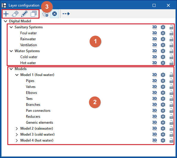
The "Layer Configuration" panel is located by default on the left side of the ‘Digital Model’ tab and offers the following controls.
Display of imported installations (1)
The display of the different installations exported from other tabs can be enabled or disabled using the options in the "Water Systems", "Sanitary Systems" and/or "Solar Systems" lines.
Display and editing of detailed models (2)
The display of the different detailed models generated with the options in the "Generate" group is managed from the lines in the "Models" section.
Editing detailed models (3)
In addition, the options in the top toolbar allow you to "Add", "Delete", "Edit" or "Copy" each of the detailed models generated.
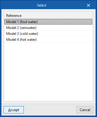
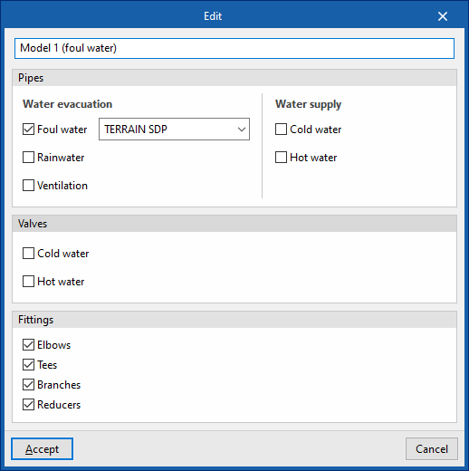
When you click on "Edit", you must choose one of the available detailed models. When you accept, the program opens a pop-up window where you can change its reference, reassign the series of materials to be used in each associated type of installation (in the "Pipes" section), and activate or deactivate the categories of fittings to be generated in the model (in the "Fittings" section).
Available options
The options on the right of this panel allow you to adjust the display and configure the capture of the elements in each category. They are as follows:
 Three-dimensional representation
Enables or disables the three-dimensional or volumetric representation of the elements in the category. Opacity
Adjusts the opacity of the 3D representation of the elements in the category. Capture
Enables or disables the capture of elements in the category.
On the other hand, the "Direction" option at the top of this panel shows the axis of the pipes together with the flow direction calculated in the "Water Systems", "Sanitary Systems" or "Solar Systems" tabs. It is necessary to adjust the opacity of the pipe layers to view it correctly.