Configuring the design and check options to be carried out on the drainage system
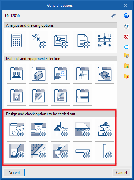
Under the "Installation" tab in the "Sanitary Systems" section, within the "General options" of the "Project" group on the main toolbar, you can configure the "Design and check options" for the following elements of the drainage system:

- Supply connection points
- Inspection box
- Fittings
- Drainage areas
- Downloads
- Drainage pipes
- Gutters
- Longitudinal drains
- Horizontal pipes
- Vertical pipes
These criteria and lists of options must be defined for each type of element before it is selected and added to the model.
If you use the "Import settings" option, located to the right of the "General options" panel, you can automatically generate this data for various national and international standards. Similarly, you can import data from different manufacturers by clicking on the options displaying their logos.
The remaining options in the right-hand column allow you to import and export the complete settings from the "General options" panel to files on your hard drive, as well as to select a file containing default values when creating a new project.
Supply connection points
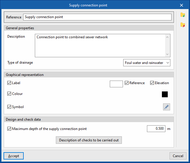
This allows you to define the supply connection points available in the project. These elements are subsequently added to the model using the "Supply connection point" option in the "Registers" group.
When defining a connection point in this section, the following parameters must be specified:
- Reference
Connection point reference. - General properties
- Description
Description of the supply connection point. - Type of drainage (Sewage / Black water / Grey water / Rainwater / Sewage and rainwater)
- Description
- Graphic representation
- Tag (optional)
- Reference (optional)
- Height (optional)
- Colour (optional)
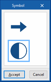
- Symbol (optional)
- Tag (optional)
- Design and check data
- Maximum depth of the supply connection point (optional)
Enables the maximum depth check for the connection point. - Description of the checks to be carried out
Allows you to enter a description of the checks to be carried out on the element. This text will appear in the reports next to each check.- Maximum depth of the connection point
- Maximum depth of the supply connection point (optional)
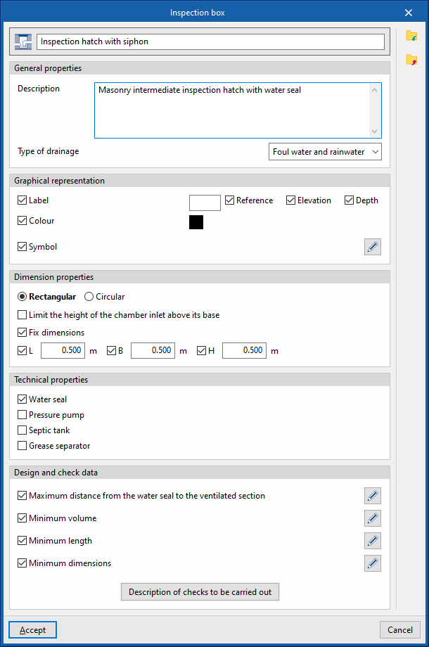
Inspection box
This allows you to define the inspection box available in the project. These elements are subsequently added to the model using the inspection box insertion options in the "Inspection box" group.
When defining a inspection box in this section, the following parameters must be specified:
- Reference
Inspection box reference. The button on the left allows you to change the associated icon if this inspection box is activated in the toolbar. - General properties
- Description
Description of the inspection box. - Type of drainage (Sewage / Black water / Grey water / Rainwater / Sewage and rainwater)
- Description
- Graphical representation
- Tag (optional)
- Reference (optional)
- Height (optional)
- Depth (optional)
- Colour (optional)
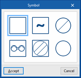
- Symbol (optional)
- Tag (optional)
- Dimension properties
- Rectangular / Circular
Defines the type of inspection box. - Limit the height of the chamber inlet above its base (optional)
Allows you to enter a maximum height for chamber inlets above their base. - Fix dimensions
- Rectangular (L, W, H)
Sets the plan dimensions (L, W) and the height (H) of the rectangular inspection box. - Circular (Diameter, Depth)
Sets the diameter and depth of the circular inspection box.
- Rectangular (L, W, H)
- Rectangular / Circular
- Technical properties
- Water seal (optional)
Allows a water seal to be specified for the component, to indicate that it is a siphon trap or a siphon pot. - Pressure pump (optional)
This option indicates that the chamber is a pumping chamber. When the chamber is subsequently added to the model, a pressure pump defined in the "Pressure pump catalogue" within the "Materials and equipment selection" section of the "General options" is selected. - Septic tank (optional)
- Grease trap (optional)
This option allows you to specify that the chamber is a grease trap. When the chamber is subsequently added to the model, a grease trap defined in the "Catalogue of grease and hydrocarbon separators and bio-filtration systems" within the "Selection of materials and equipment" section of the "General options" is selected. - Excavations (optional)
Allows you to select an inspection box excavation profile defined under "Inspection box", within "Excavations", in the "Design options" section of the "General options". This enables the program to analyse the excavation volumes for the inspection box.
- Water seal (optional)
- Design and check data
- Maximum distance from the water seal to the ventilated section (optional)
This allows you to enable the check for the maximum distance between the hydraulic gate and the ventilated section based on the slope. - Minimum volume (optional)
Allows you to enable the minimum volume check for the inspection box by selecting one of the following calculation expressions:- V = 0.3 × Q
- V = 0.9 × Q / N,
Where N is the number of starts per hour of the pressure pump. - V = Q × t / 4, where
Where t is the time interval.
- Minimum length (optional)
Enables the maximum distance between the hydraulic seal and the ventilated section to be checked based on the depth. - Minimum dimensions (optional)
This option enables the analysis of the minimum dimensions of the inspection box (length and width or diameter) based on the nominal diameter of the outlet sewer, which can be defined when inserting a inspection box element into the model.
- Maximum distance from the water seal to the ventilated section (optional)
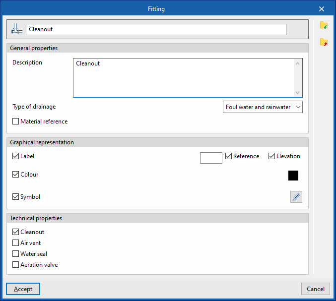
Fittings
This allows you to define the fittings available in the project, such as cleaning access panels, ventilation outlets and ventilation valves. These elements are subsequently added to the model using the fitting insertion options in the "Access panels" group.
When defining a fitting in this section, you must specify the following parameters:
- Reference
Fitting reference. The button on the left allows you to change the associated icon if this accessory is activated in the toolbar. - General properties
- Description
Description of the fitting. - Type of drainage (Sewage / Black water / Grey water / Rainwater / Sewage and rainwater)
- Material reference (optional)
Allows you to select a material for the fitting defined in the "Fittings catalogue" within the "Materials and equipment selection" section of the "General options".
- Description
- Graphic representation
- Label (optional)
- Reference (optional)
- Elevation (optional)
- Colour (optional)
- Symbol (optional)
- Label (optional)
- Technical properties
This allows you to specify whether the fitting is a cleaning port, an aeration outlet, a hydraulic shut-off valve or an aeration valve.- Cleanout (optional)
- Air vent (optional)
- Water seal (optional)
- Aeration valve (optional)
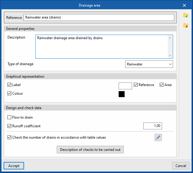
Drainage areas
This allows you to define the drainage areas available in the project. These elements are subsequently added to the model using the "Drainage area" option in the "Outlets" group.
When defining a catchment area in this section, you must specify the following parameters:
- Reference
Drainage area reference. - General properties
- Description
Description of the drainage area. - Type of drainage (Sewage / Black water / Grey water / Rainwater / Sewage and rainwater)
- Description
- Graphic representation
- Label (optional)
- Reference (optional)
- Area (optional)
- Colour (optional)
- Label (optional)
- Design and check data
- Drainage flow rate (optional)
Allows you to specify the drainage flow rate per unit area of the drainage catchment. - Runoff coefficient (optional)
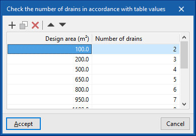
Allows you to apply a runoff coefficient that regulates the volume of water drained by the catchment area. - Check the number of drains against table values (optional)
This allows you to enable a check of the number of drains located in the drainage area based on the projected area. - Description of the checks to be carried
out Allows you to enter a description of the checks to be carried out on the element. This text will appear in the lists next to each check.- Check the number of drains against the values in the table
- Drainage flow rate (optional)
Downloads
This allows you to define the loads available in the project. These elements can then be added to the model using the options in the "Loads" group.
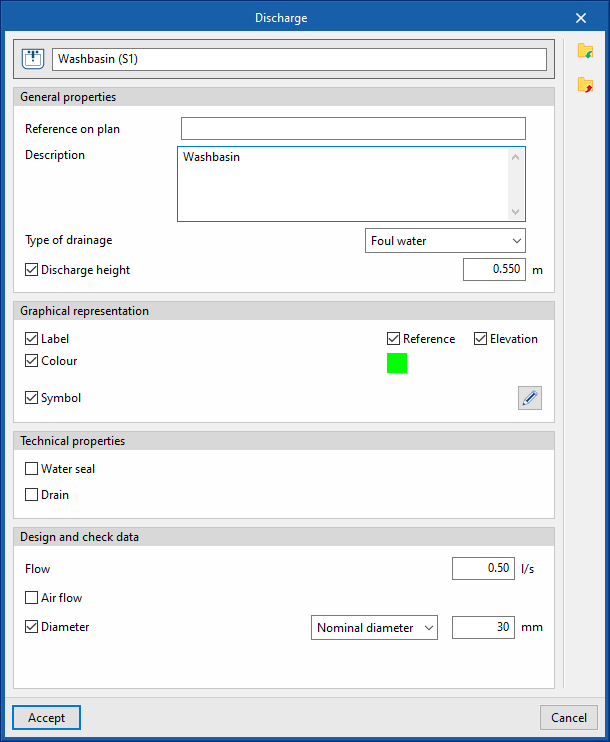
When defining a download in this section, you must specify the following parameters:
- Reference
Download reference. The button on the left allows you to change the associated icon if this download is activated in the toolbar. - General properties
- Reference on the map
- Description
Description of the download. - Type of drainage (Sewage / Black water / Grey water / Rainwater / Sewage and rainwater)
- Discharge height (optional)
Defines a discharge height as a positive value, measured from the point where the element is inserted into the model.
- Graphic representation
- Tag (optional)
- Reference (optional)
- Height (optional)
- Colour (optional)
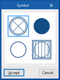
- Symbol (optional)
- Tag (optional)
- Technical properties
- Water seal (optional)
Indicates that the discharge is fitted with a water seal. - Drain (optional)
Allows you to specify that the discharge is a point drain. In this case, you can select a material from those defined in the "General options", under "Selection of materials and equipment", and from the "Drain catalogue".- Material (optional)
- Water seal (optional)
- Design and check data
- Drainage units
: Allows you to specify the number of drainage units associated with the discharge. This option only appears if the "Discharge values defined in drainage units" checkbox is ticked; this can be accessed via the "Calculation options" section of the "General options". - Projected area (optional)
Allows you to override the projected area associated with a discharge defined as a drain. This option only appears if the "Drain" checkbox in this panel is ticked and the "Discharge values defined in drainage units" checkbox, accessible from the "Calculation options" section of the "General options", is ticked. - Flow rate (optional)
Allows you to set the flow rate associated with the discharge. If this option is left disabled, the flow rate can be set when entering each discharge item using the options in the "Discharges" group on the main interface. - Air flow rate (optional)
Allows you to set the air flow rate associated with the discharge. - Diameter (optional)
Allows you to specify the following diameters associated with the discharge.- Nominal diameter
- Outer diameter
- Inner diameter
- Maximum distance between the hydraulic closure and the ventilated section (optional)
This allows you to enable the check for the maximum distance between the hydraulic closure and the ventilated section based on the slope. This option is only available if the "Hydraulic closure" checkbox is ticked in this panel.
- Drainage units
Drainage pipes
This allows you to define the drainage pipes available in the project. These elements can subsequently be added to the model using the "Drainage pipe" option within the "Pipes" group.
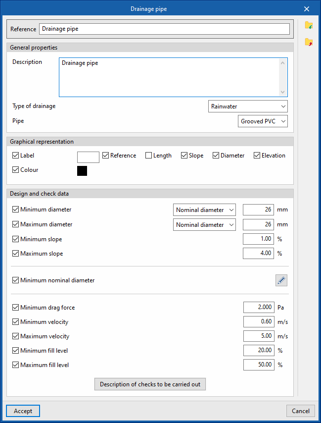
When defining a drainage pipe in this section, you must specify the following parameters:
- Reference
Drainage pipe reference. - General properties
- Graphic representation
- Tag (optional)
- Reference (optional)
- Length (optional)
- Earring (optional)
- Diameter (optional)
- Height (optional)
- Colour (optional)
- Tag (optional)
- Design and check data
- Minimum diameter (optional)
Allows you to specify the minimum diameter (nominal, external or internal) of the drainage pipe. - Maximum diameter (optional)
Allows you to specify the maximum diameter (nominal, external or internal) of the drainage pipe. - Minimum slope (optional)
The minimum gradient that the drainage pipe must have to ensure self-cleaning conditions. - Maximum slope (optional)
The maximum permissible gradient that the drainage pipe may have. - Minimum nominal diameter (optional)
Allows you to specify the minimum nominal diameter of the drainage pipe by adding entries to a table based on the degree of impermeability, the pipe’s slope and its layout (underground or along the perimeter of the wall). These details are subsequently specified for each drainage pipe added to the model using the “Drainage pipe” option in the “Pipes” group.- Waterproofing rating / Minimum gradient / Maximum gradient / Nominal diameter (underfloor drains) / Nominal diameter (perimeter wall drains)
- Minimum drag force; Minimum velocity; Maximum velocity; Minimum fill level; Maximum fill level
This set of options allows you to configure the values associated with the hydraulic calculation checks and only appears if the "Hydraulic analysis" option is enabled in the "Design options" section of the "General options". - Description of the checks to be carried out
Allows you to enter a description of the checks to be carried out on the element. This text will appear in the reports next to each check.- "General data" tab (Minimum nominal diameter, Maximum nominal diameter, Minimum gradient, Maximum gradient). This tab only appears if the relevant options are selected in the previous editing panel.
- "Design by tables" tab (Diameter, Slope)
This tab only appears if the "Design by tables" option is enabled in the "Design options" section of the "General options". - "Hydraulic analysis" tab (Drag force, Minimum velocity, Maximum velocity, Minimum water level, Maximum water level, Hydraulic capacity)
This tab only appears if the "Hydraulic analysis" option is enabled in the "Design options" section of the "General options".
- Minimum diameter (optional)
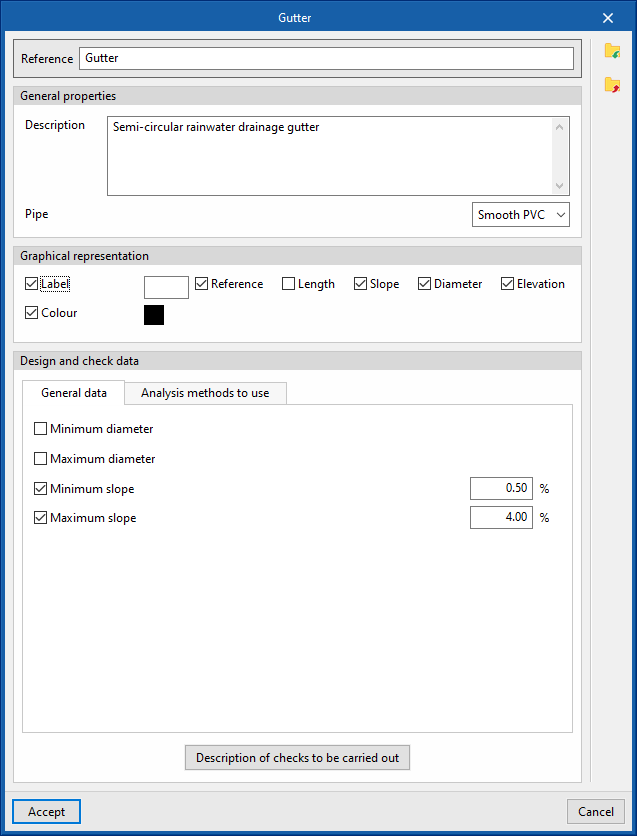
Gutters
This allows you to define the gutters available in the project. These elements can subsequently be added to the model using the "Gutter" option within the "Pipes" group.
When defining a gutter in this section, you must specify the following parameters:
- Reference
Gutter reference. - General properties
- Description
Description of the gutter. - Piping
Select a material from those listed in the "Gutter catalogue", under the "Materials and equipment selection" section of the "General options".
- Description
- Graphic representation
- Tag (optional)
- Reference (optional)
- Length (optional)
- Slope (optional)
- Diameter (optional)
- Elevation (optional)
- Colour (optional)
- Tag (optional)
- Design and check data
- "General Information" tab
- Minimum diameter (optional)
Allows you to specify the minimum diameter (nominal, external or internal) of the gutter. - Maximum diameter (optional)
Allows you to specify the maximum diameter (nominal, external or internal) of the gutter. - Minimum slope (optional)
The minimum slope that the gutter must have to ensure self-cleaning conditions. - Maximum slope (optional)
The maximum permissible slope that the gutter can have.
- Minimum diameter (optional)
- "Analysis methods to use" tab
- "Design using tables" tab
- Drainage units / Area / Flow
rate
This allows you to define, in a series of tables, the nominal diameter to be used for each value of the number of drainage units, projected area or flow rate of water discharged, and for each gradient value. The program calculates the diameter of the elements based on this configuration if "Design using tables" is selected in the "Design options" section of the "General options".
- Drainage units / Area / Flow
- "Hydraulic analysis" tab
- Minimum head, Minimum velocity, Maximum velocity, Minimum fill level, Maximum fill level
This set of options configures the values associated with the hydraulic analysis checks and only appears if the "Hydraulic analysis" option is enabled in the "Design options" section of the "General options".
- Minimum head, Minimum velocity, Maximum velocity, Minimum fill level, Maximum fill level
- "Design using tables" tab
- Description of the checks to be carried out
Allows you to enter a description of the checks to be carried out on the element. This text will appear in the lists next to each check.- "General data" tab (Minimum nominal diameter, Maximum nominal diameter, Minimum gradient, Maximum gradient). This tab only appears if the relevant options are selected in the previous editing panel.
- "Design using tables" tab (Drainage units / Projected area / Flow rate, Diameter, Gradient)
This tab only appears if the "Design using tables" option is enabled in the "Design options" section of the "General options". - "Hydraulic analysis" tab (Drag force, Minimum velocity, Maximum velocity, Minimum water level, Maximum water level, Hydraulic capacity)
This tab only appears if the "Hydraulic analysis" option is enabled in the "Design options" section of the "General options".
- "General Information" tab
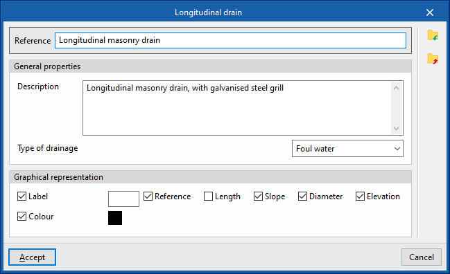
Longitudinal drains
This allows you to define the longitudinal drains available in the project. These elements can subsequently be added to the model using the "Longitudinal drain" option within the "Pipes" group.
When defining a longitudinal drain in this section, the following parameters must be specified:
- Reference:
Reference for the longitudinal drain. - General properties
- Description
Description of the longitudinal drain. - Type of drainage (Sewage / Black water / Grey water / Rainwater / Sewage and rainwater)
- Description
- Graphic representation
- Label (optional)
- Reference (optional)
- Length (optional)
- Slope (optional)
- Diameter (optional)
- Height (optional)
- Colour (optional)
- Label (optional)
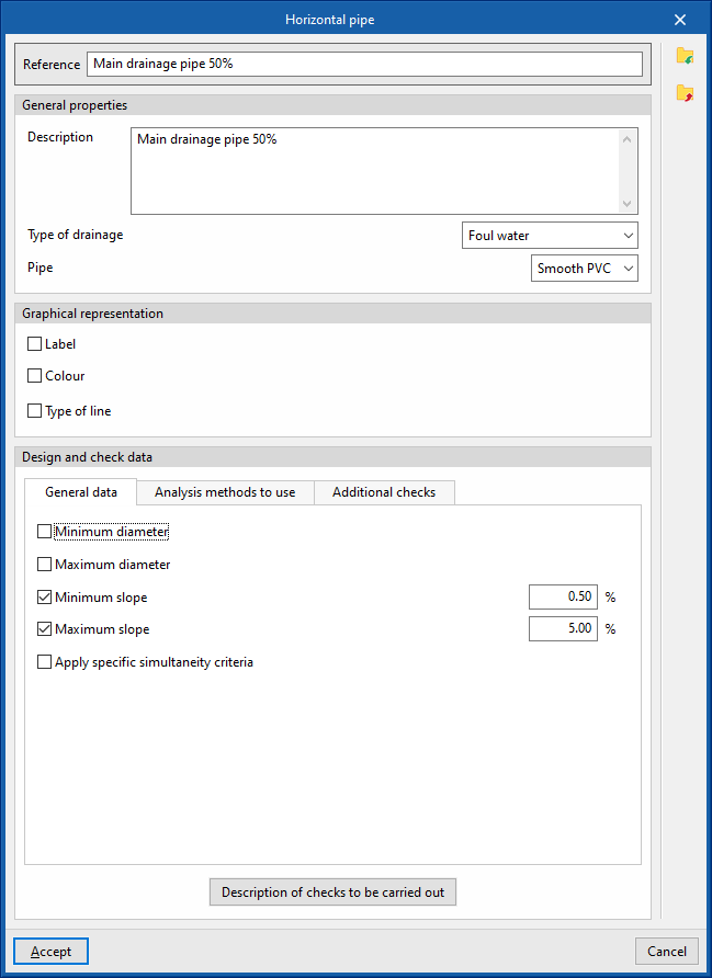
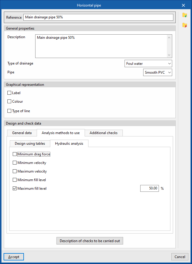
Horizontal pipes
This allows you to define the horizontal pipes in the project. These elements can subsequently be added to the model using the options in the "Pipes" group.
When defining a horizontal pipe in this section, you must specify the following parameters:
- Reference:
Reference for the horizontal pipe. - General properties
- Description
Description of the horizontal pipe. - Drainage type (Sewage / Black water / Grey water / Stormwater / Sewage and stormwater / Ventilation)
Selects the type of drainage. This includes the option to define a ventilation pipe. - Piping
Selects a material from those defined in the "Pipe catalogue" under the "Materials and equipment selection" section of the "General options".
- Description
- Graphical representation
- Label (optional)
- Reference (optional)
- Length (optional)
- Slope (optional)
- Diameter (optional)
- Height (optional)
- Colour (optional)
- Type of line (optional)
- Label (optional)
- Technical properties
- Excavations (optional)
Selects a horizontal pipe excavation profile defined under "Horizontal pipes" within "Excavations" in the "Calculation options" section of "General options". In this way, the program is able to calculate the excavation volumes for the horizontal pipe.
- Excavations (optional)
- Design and check data
- "General data" tab
- Minimum diameter (optional)
Specifies the minimum diameter (nominal, external or internal) of the pipe. - Maximum diameter (optional)
Specifies the maximum diameter (nominal, external or internal) of the pipe. - Minimum slope (optional)
The minimum gradient that the pipe must have to ensure self-cleaning conditions. - Maximum slope (optional)
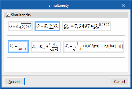
The maximum permissible slope that the pipe can have. - Apply specific simultaneity criteria (optional)
Applies specific simultaneity criteria for the pipeline instead of those defined under "Simultaneity" in the "Design options" section of the "General options".- Q = K (Σ UD)¹/²
This formula allows you to calculate the simultaneous flow rate (Q) based on the sum of discharge units (UD) and the coefficient K. This coefficient can be entered in the box immediately below. The wizard on the right allows you to import default values for the coefficient K for different loadcases involving the use of sanitary appliances. - Q = Kn Σ Q
i This formula allows the total flow rate (Q) to be calculated based on the sum of the instantaneous flow rates (Qi) and the Kn coefficient. This coefficient depends on the number n of outlets, and its calculation formula takes various forms, which are displayed and can be selected in this section. - Qc = 7.3497 × Qa⁰.⁵³⁵²
This formula allows the simultaneous or design flow rate (Qc) to be calculated based on the cumulative flow rate (Qa).
- Q = K (Σ UD)¹/²
- Minimum diameter (optional)
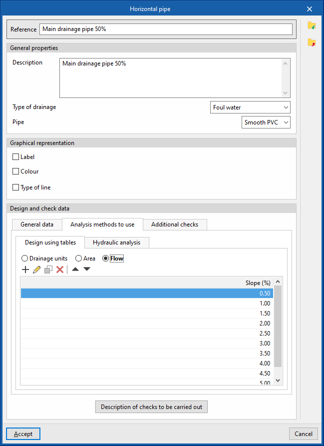
- "Analysis methods to use" tab
- "Table-based sizing" tab
- Drainage units / Area / Flow
rate
Defines, in a series of tables, the nominal diameter to be used for each value of the number of drainage units, projected area or flow rate of water discharged, and for each gradient value. The program calculates the diameter of the elements based on this configuration if "Design using tables" is selected in the "Design options" section of the "General options".
- Drainage units / Area / Flow
- "Hydraulic analysis" tab
- Minimum head, Minimum velocity, Maximum velocity, Minimum fill level, Maximum fill level (optional)
This set of options sets the values associated with the hydraulic analysis checks and only appears if the "Hydraulic analysis" option is enabled in the "Design options" section of the "General options".
- Minimum head, Minimum velocity, Maximum velocity, Minimum fill level, Maximum fill level (optional)
- "Table-based sizing" tab
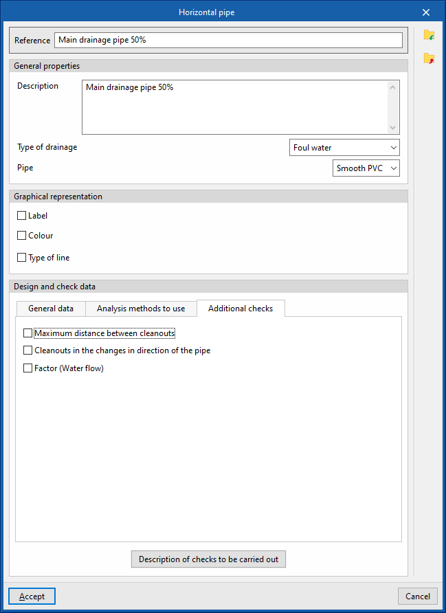
- "Additional checks" tab
Defines the following additional checks to be carried out on the pipework.- Maximum distance between cleanout (optional)
- Cleanouts in the changes in the direction of the pipe (optional)
- Factor (Water flow) (optional)
- Description of the checks to be carried out
Enters a description of the checks to be carried out on the element. This text will appear in the lists next to each check.- "General data" tab (Minimum nominal diameter, Maximum nominal diameter, Minimum gradient, Maximum gradient). This tab only appears if the relevant options are selected in the previous editing panel.
- "Design using tables" tab (Diameter, Slope)
This tab only appears if the "Dimensioning by Tables" option is enabled in the "Calculation Options" section of the "General Options". - "Hydraulic analysis" tab (Drag force, Minimum velocity, Maximum velocity, Minimum water level, Maximum water level, Slope, Hydraulic capacity)
This tab only appears if the "Hydraulic analysis" option is enabled in the "Design options" section of the "General options".
- "General data" tab
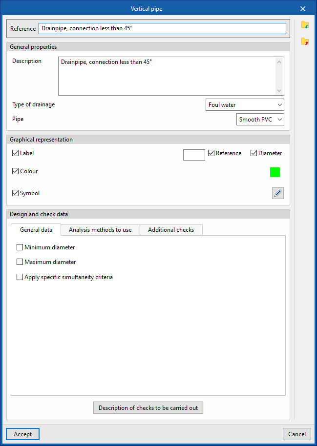
Vertical pipes
Defines the vertical pipes in the project. These elements can subsequently be added to the model using the options in the "Pipes" group.
When defining a vertical pipe in this section, you must specify the following parameters:
- Reference:
Reference for the vertical pipe. - General properties
- Description
Description of the vertical pipe. - Drainage type (Sewage / Black water / Grey water / Stormwater / Sewage and stormwater / Ventilation)
Allows you to select the type of drainage. This includes the option to define a ventilation pipe. - Pipe
Select a material from those defined in the "Pipe catalogue" under the "Materials and equipment selection" section of the "General options".
- Description
- Graphic representation
- Label (optional)
- Reference (optional)
- Length (optional)
- Slope (optional)
- Diameter (optional)
- Height (optional)
- Colour (optional)
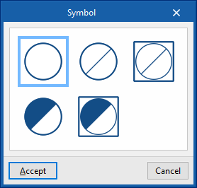
- Symbol (optional)
- Label (optional)
- Design and check data
- "General properties" tab
- Minimum diameter (optional)
Allows you to specify the minimum diameter (nominal, external or internal) of the pipe. - Maximum diameter (optional)
Allows you to specify the maximum diameter (nominal, external or internal) of the pipe. - Apply specific simultaneity criteria (optional)
Allows you to apply specific simultaneity criteria for the pipe instead of those defined under "Simultaneity", which is located within the "Design options" section of "General options".- Q = K (Σ UD)¹/²
This formula allows you to calculate the simultaneous flow rate (Q) based on the sum of discharge units (UD) and the coefficient K. This coefficient can be entered in the box immediately below. The wizard on the right allows you to import default values for the coefficient K for different laodcases involving the use of sanitary appliances. - Q = Kn Σ Q
i This formula allows the total flow rate (Q) to be calculated based on the sum of the instantaneous flow rates (Qi) and the Kn coefficient. This coefficient depends on the number n of outlets, and its calculation formula takes various forms, which are displayed and can be selected in this section. - Qc = 7.3497 × Qa⁰.⁵³⁵²
This formula allows the simultaneous or design flow rate (Qc) to be calculated based on the cumulative flow rate (Qa).
- Q = K (Σ UD)¹/²
- Minimum diameter (optional)
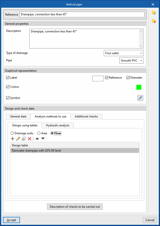
- "Analysis methods to use" tab
- "Design using tables" tab
- Drainage units / Area / Flow rate
This allows you to define, in a series of tables, the nominal diameter for each value of the number of drainage units, projected area or discharged water flow rate, and for each gradient value. The program calculates the diameter of the elements based on this configuration if “Design using tables” is selected in the “Design options” section of the “General options”. It also offers the following additional options:- Maximum number of floors (optional)
Allows you to specify the maximum number of storeys in the vertical pipe. - Fix the maximum number of units in each branch (optional)
This allows you to set the maximum number of drainage units, the maximum projected area or the maximum flow rate of water discharged in each branch.
- Maximum number of floors (optional)
- Drainage units / Area / Flow rate
- "Hydraulic analysis" tab
- Maximum fill level (optional)
This option allows you to set the value used for the maximum fill level check and only appears if the "Hydraulic analysis" option is enabled in the "Design options" section of the "General options".
- Maximum fill level (optional)
- "Design using tables" tab
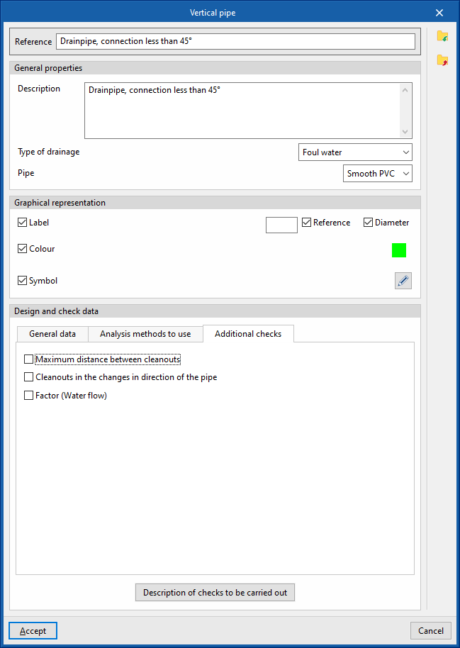
- "Additional checks" tab
Defines the following additional checks to be carried out on the pipe.- Maximum distance between records (optional)
- Records of changes in the direction of the pipe (optional)
- Factor (Water flow) (optional)
- Description of the checks to be carried out
Enters a description of the checks to be carried out on the element. This text will appear in the lists next to each check.- Minimum nominal diameter, Maximum nominal diameter, Fill level, Hydraulic
capacity
These fields only appear if the relevant options are selected in the previous editing panel and the "Hydraulic analysis" option is selected in the "Design options" section of the "General options".
- Minimum nominal diameter, Maximum nominal diameter, Fill level, Hydraulic
- "General properties" tab