Automatic generation of the drainage system layout
The program includes several utilities that enable the automatic layout of pipes for different parts of the drainage system in the "Sanitary Systems" tab. The geometry proposed after the automatic layout generation process can be adjusted and modified later to suit the project requirements.
Options in the "Generation" group
The options for automatic pipe layout generation are located in the new "Generation" group, in the "Installation" tab.

The available tools are shown in ascending order of complexity and are as follows.
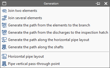
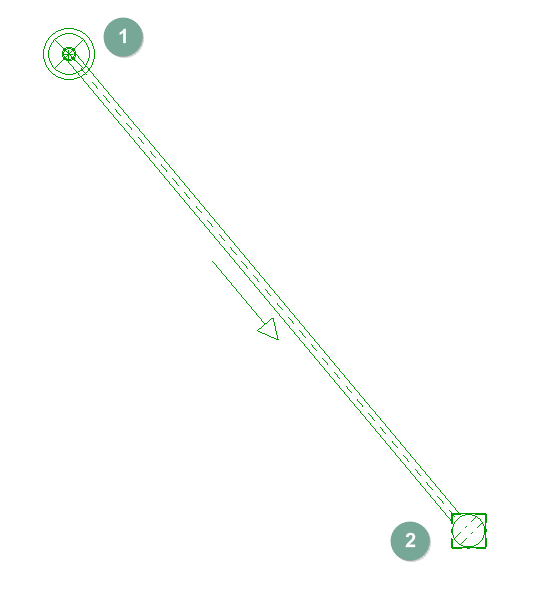
Join two elements
Generates a pipe between two elements selected with the left button in the model.
- Examples:
- Generation of the pipe between a "Drain" (1) and a "Floor trap" (2).
- Generation of the pipe between two inspection boxes.
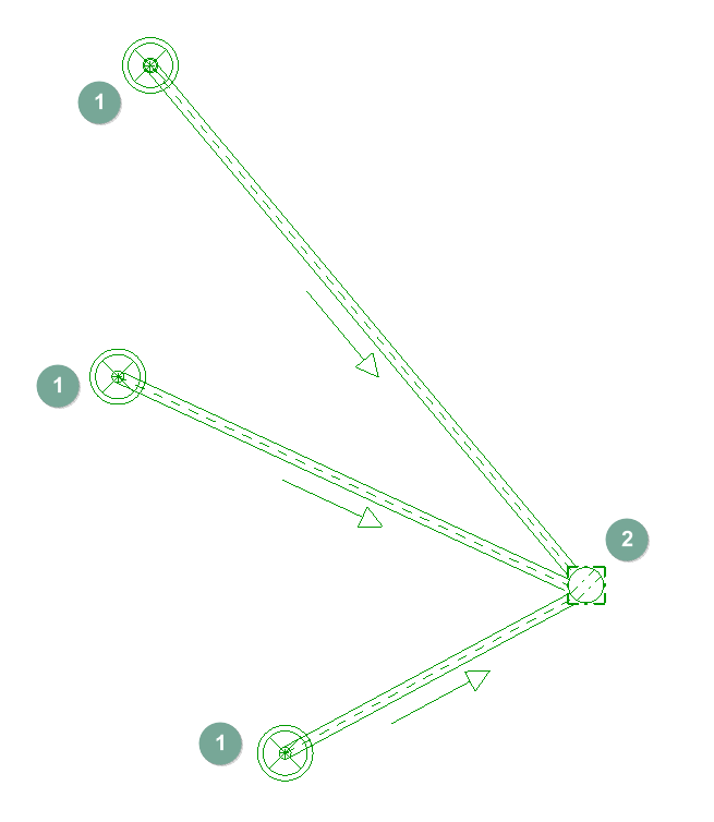
Join several elements
Generates several pipes between the elements selected in the model.
- Sequence of use:
- Manual placement of the elements to be joined (for example, several drains from a wet room and a floor trap).
- Click on the "Join several elements" option.
- Select the source elements of the pipes with the left mouse button; in this case, the drains (1).
- Right-click to confirm the previous selection.
- Select the destination element of the pipes with the left mouse button; in this case, the floor trap (2). At this point, the pipes connecting the elements are generated.
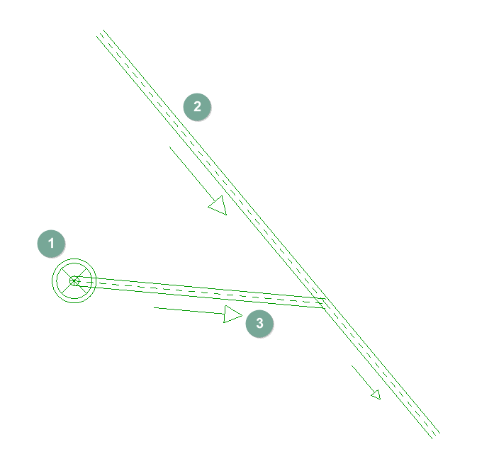
Generate the path from the elements to the branch
Generates the individual pipes from the selected drains to a controlled layout branch (which must be previously entered in the desired position).
- Sequence of use:
- Manual placement of the source elements of the pipes, such as the discharges (1).
- Manual insertion of the branch pipe (2) following the geometry desired by the user.
- Click on the "Generate the path from the elements to the branch" option.
- Left-click on the source elements of the pipes (1).
- Right-click to confirm the previous selection.
- Left-click to select the manually inserted branch (2). As a result, the individual pipes (3) are automatically generated from the outlets to the branch, connecting to it at 45 degrees.
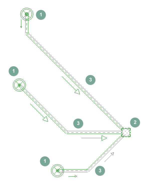
Generate the path from the discharges to the inspection box
Generates the pipes from the selected discharges to a manhole type element, based on the number of connections allowed in this element.
| Note: |
|---|
| The number of connections or pipe inlets available in the manhole type element is defined in "General options" > "Design options and checks to be carried out" > "Inspection boxes" > "Dimensional characteristics" > "Set the connections". In the case of floor traps, it is also necessary to define here that the element is "Small discharge" |
- Sequence of use:
- Manual placement of the discharges (1).
- Manual arrangement of the "Inspection box" type element (such as a floor trap) (2).
- Click on the "Generate the path from the discharges to the inspection box" option.
- Select the source elements of the pipes with the left button (1).
- Right-click to confirm the previous selection.
- Left-click to select the inspection box-type element (such as the floor trap) (2) entered manually. As a result, the pipes from the discharges to the available connections of the inspection box-type element (3) are automatically generated and distributed radially around it.
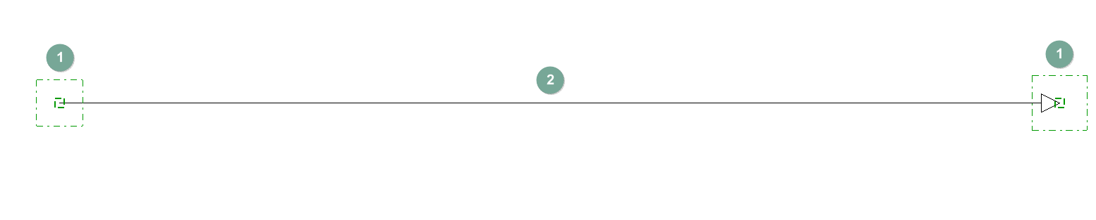
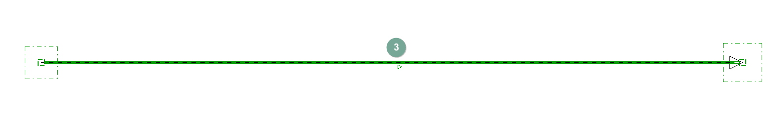
Generate the path along the horizontal pipe layout
Generates the pipes following a controlled horizontal layout, which must be entered beforehand in the desired position.
- Sequence of use:
- Manual placement of elements (e.g. two manholes) (1).
- Manual insertion of the "Horizontal pipe layout" (2) between the centres of the elements, following the geometry and direction desired by the user (in this example, the layout is placed from the centre of one inspection box to another).
- Click on the "Generate the path along the horizontal pipe route" option.
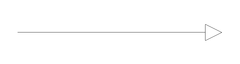
- Select the horizontal pipe route with the left button. As a result, the pipe (3) is automatically generated between the elements following the selected route.
| Note: |
|---|
| This working method ensures better resolution of the connections between the pipes and the elements. |
Generate the path along the service riser
Generates a pipe following a vertical pipe passage (or duct), which must be previously entered in the desired position.
- Sequence of use:
- Manual entry of the "Vertical pipe passage".
- Click on the option "Generate the path along the shafts".
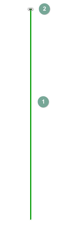
- Select the vertical pipe passage with the left button. As a result, the pipe (1) is automatically generated following the layout of the duct. In addition, the program provides an "Aeration terminal" (2) at its upper end.
Before generation, the discharges can be manually entered in their position or generated by reading the BIM model, if it has information on the sanitary appliances. The rest of the elements needed for generation (main branch pipe, inspection boxes or floor traps, horizontal layouts and vertical pipe passages) must be entered manually before using the above options.
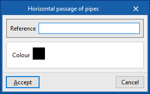
Horizontal pipe layout
This can indicate the horizontal layout of the pipes between two elements, so that it can be used later in the generation processes.
When entering a horizontal pipe layout, the following data must be specified:
- Reference
Reference for the horizontal pipe layout. - Color
Representation colour.
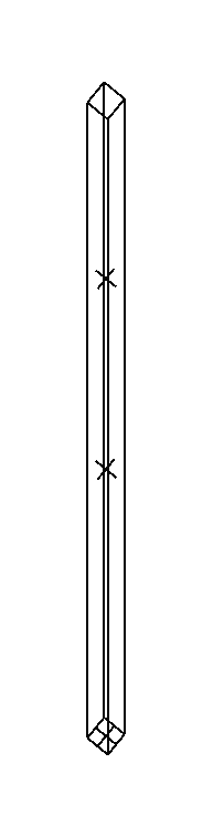
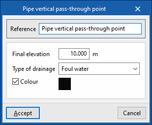
Pipe vertical pass-through point
This can indicate the position of a pipe shaft or vertical pipe passage for later use in the generation processes.
When entering a vertical pipe passage, the following data must be specified:
- Reference
Reference for the vertical pipe passage. - Drainage type
Select the drainage type from the following:- Wastewater / Foul water / Grey water / Rainwater / Wastewater or rainwater
- Final elevation
Final elevation of the vertical pipe passage in absolute coordinates. - Colour
Display colour.
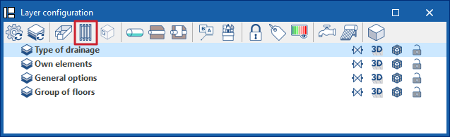
Related options in the "Layer settings" panel
The toolbar in the "Layer settings" panel offers a specific option to control the display of horizontal pipe routes and vertical pipe passages entered in the model.