Configuring the design and check options to be carried out during the installation of a solar thermal system
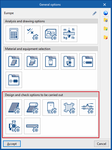
Under the "Installation" tab in the "Solar Systems" section, within the "General options" of the "Project" group on the main toolbar, you can configure the "Sizing options and checks to be performed" for the following components of the solar thermal installation:

- Solar thermal collectors
- Solar thermal collectors with a storage tank
- Batteries
- Heat exchangers
- Accessories
- Pumps
- Pipes
These criteria or options for designs and checks must be defined for each type of element before it is selected and added to the model.
If you use the "Import settings" option, located to the right of the "General options" panel, you can automatically generate this data for different countries and national and international regulations.
The remaining options in the right-hand column allow you to import and export the complete settings from the "General options" panel to files on your hard drive, as well as to select a file containing default values when creating a new project.
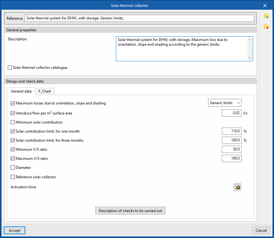
Solar thermal collectors / Solar thermal collectors with storage
This allows you to define the design and check options for solar thermal collectors and solar thermal collectors with storage tanks available in the project. These options are selected when these elements are subsequently added to the model, using the "Solar thermal collector" or "Solar thermal collector with storage tank" options in the "Solar collection" group.
When defining the design and check options for each of these elements, the following parameters must be specified:
- Reference
- General features
- Description
- Solar thermal collector catalogue (optional)
You can link the criterion to one of the materials or items of equipment previously defined in the solar thermal collector catalogue, via the "Solar collector catalogue with storage tank" option, which can be found under "Solar thermal collector catalogue" in the "General options".
- sizing and verification data
- "General Information" tab
- Maximum losses due to orientation, slope and shading (optional)
You can select one of the predefined losses from the "General Checks" section of the "General Options". - Enter flow rate per m2 surface area (optional)
- Minimum solar contribution (optional)
The minimum ratio between the amount of solar energy supplied and the energy demand. - Maximum solar contribution for one month (optional)
The maximum ratio between the amount of solar energy supplied and energy demand over a month. - Maximum solar contribution for three months (optional)
The highest ratio between the amount of solar energy supplied and energy demand over three months. - Minimum V/S ratio (optional)
The minimum required ratio between the storage volume and the catchment area. - Maximum V/S ratio (optional)
The maximum permissible ratio between the storage volume and the catchment area. - Diameter (optional)
- Reference solar thermal collector (optional)
Defining a reference solar thermal collector requires the following data to be entered: Azimuth, Tilt, Effective area per subscriber, η0, a1, a2, IAM. - Activation time
Defined by the number of active hours in each month of the year. - Description of checks to be carried out
Allows you to enter a description of the checks to be carried out on the element. This text will appear in the lists next to each check.- Daily volume
- Maximum solar contribution for one month
- Maximum solar contribution for three months
- V/S ratio
- Loss due to orientation or slope
- Shadow losses
- Total losses
- Maximum losses due to orientation, slope and shading (optional)
- "General Information" tab
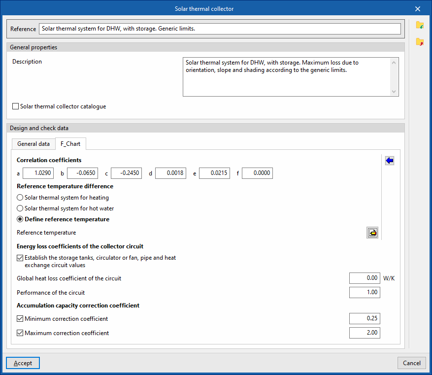
- "F_Chart" tab:
Allows you to set the parameters required to calculate solar collectors using the F-chart method.- Correlation coefficients (a, b, c, d, e, f)
Allows you to modify the coefficients of the expressions used in the method. - Reference temperature difference
The values for the reference temperature difference and the correlation coefficients can be loaded automatically using the wizard on the right, for both a "Direct system" and a "Storage system".- Solar thermal system for heating
- Solar thermal system for hot water
- Define reference temperature
Allows you to enter the "reference temperature" for each month of the year.
- Energy loss coefficients of the collector circuit
- Set the circuit values for the manifolds, circulators or fans, pipes and heat exchangers (optional)
- Global heat loss coefficient of the circuit
- Performance of the circuit
- Set the circuit values for the manifolds, circulators or fans, pipes and heat exchangers (optional)
- Accumulation capacity correction coefficient
- Minimum correction factor (optional)
- Maximum correction factor (optional)
- Correlation coefficients (a, b, c, d, e, f)
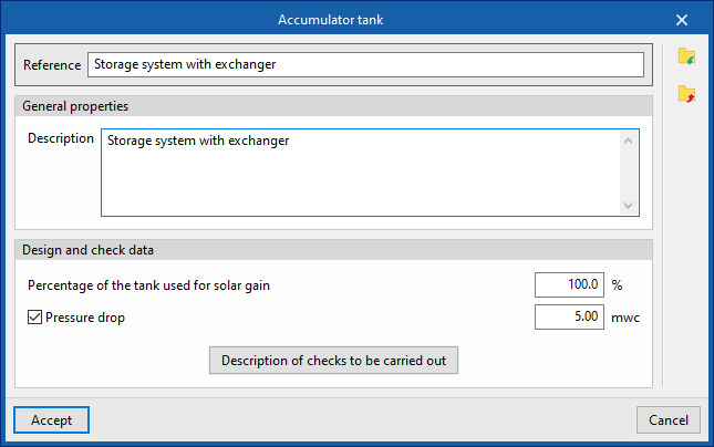
Batteries
This allows you to define the design and check options for storage tanks available in the project. These options are selected when these elements are subsequently added to the model, using the "Storage tank" option in the "Demand" group.
When configuring these options, you must specify the following parameters:
- Reference
- General features
- Description
- Design and check data
- Percentage of the tank used for solar gain
- Pressure drop (optional)
The pressure drop associated with the tank. - Description of checks to be carried out
Allows you to enter a description of the checks to be carried out on the element. This text will appear in the lists next to each check.- Daily volume
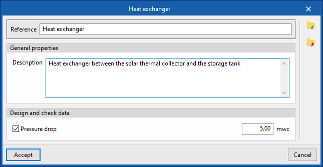
Heat exchangers
This allows you to define the heat exchanger sizing and verification options available in the project. These options are selected when these elements are subsequently added to the model, using the "Heat exchanger" option in the "Demand" group.
When configuring these options, you must specify the following parameters:
- Reference
- General features
- Description
- Design and check data
- Pressure drop (optional)
The pressure drop associated with the heat exchanger.
- Pressure drop (optional)
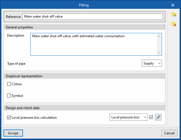
Fittings
This allows you to define the design and check options for fittings available in the project. These elements can subsequently be added to the model using the "Fitting" option within the "Hydraulic circuit" group.
When configuring these options, you must specify the following parameters:
- Reference
- General features
- Description
- Pipe type (Supply / Return)
- Graphic representation
- Colour (optional)
- Symbol (optional)
- Design and check data
- Local pressure loss calculation (optional)
This allows you to enable the calculation of localised pressure drop in the fitting and define the calculation criteria by selecting one of the available options:- Local pressure loss
- Equivalent length
- Local pressure loss calculation (optional)
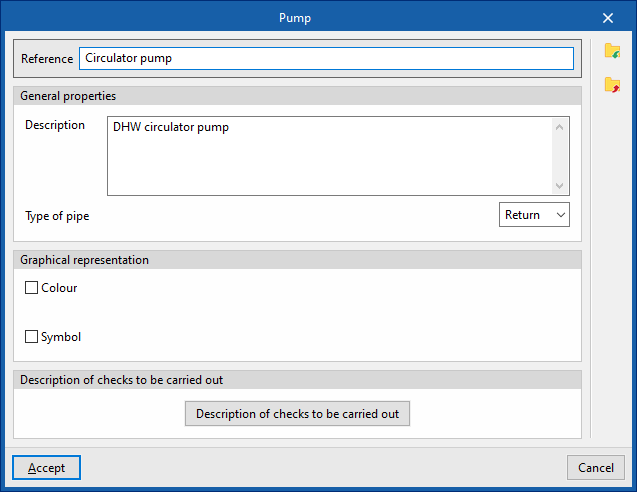
Pumps
This allows you to define the pump design and check options available in the project. These elements are subsequently added to the model using the "Pump" option in the "Hydraulic circuit" group.
When configuring these options, you must specify the following parameters:
- Reference
- General features
- Description
- Pipe type (Supply / Return)
- Graphic representation
- Colour (optional)
- Symbol (optional)
- Design and check data
- Description of the checks to be carried out
Allows you to enter a description of the checks to be carried out on the element. This text will appear in the reports next to each check.- Increase in pressure
- Description of the checks to be carried out
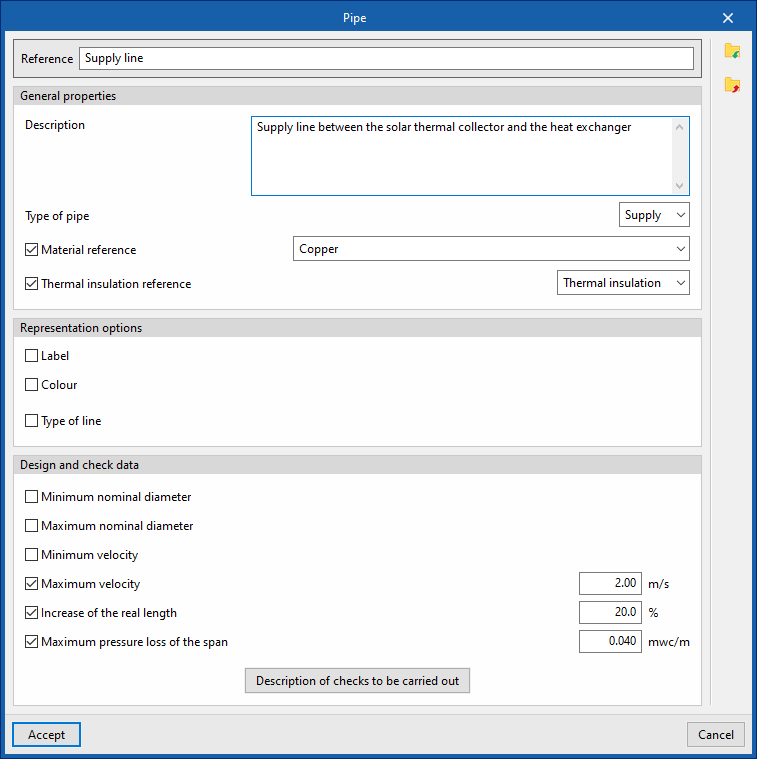
Pipes
This allows you to define the piping design and check the options available in the project. These elements are subsequently added to the model using the options available within the "Hydraulic circuit" group, such as "Pipe".
When configuring these options, you must specify the following parameters:
- Reference
- General features
- Description
- Type of pipe (Supply / Return)
- Material reference
This allows you to select one of the materials listed in the "Pipe catalogue" table, under the "Material and equipment selection" section of the "General options". - Thermal insulation reference
This allows you to select one of the materials listed in the "Thermal insulation catalogue" table, under the "Selection of materials and equipment" section of the "General options".
- Graphic representation
- Tag (optional)
- Reference (optional)
- Diameter (optional)
- Insulation (optional)
- Colour (optional)
- Line type (optional)
- Tag (optional)
- Design and check data
- Minimum nominal diameter (optional)
The minimum permissible nominal diameter of the pipe. - Maximum nominal diameter (optional)
The maximum permissible nominal diameter of the pipe. - Minimum velocity (optional)
Minimum permissible fluid velocity in the section. - Maximum velocity (optional)
Maximum permissible fluid velocity in the section. - Increase of the real length (optional)
Allows you to apply a percentage increase to the actual length of the pipe based on the length entered in the model. - Maximum pressure loss of the span (optional)
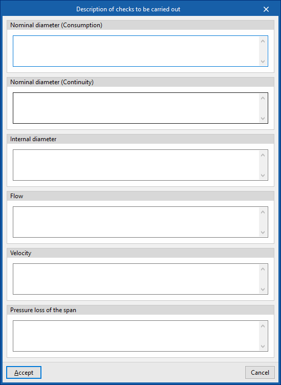
Maximum permissible pressure drop in the pipe section. - Description of the checks to be carried out
Allows you to enter a description of the checks to be carried out on the element. This text will appear in the lists next to each check.- Nominal diameter (Consumption)
- Nominal diameter (Continuity)
- Inner diameter
- Flow rate
- Velocity
- Pressure loss in the span
- Minimum nominal diameter (optional)