
Entering infrastructure elements into the BIM model
The main toolbar of the "3D Model" tab contains the "Infrastructure" group, which provides the tools needed to define the spatial position of telecommunications infrastructure elements in the BIM model through a 3D working environment. From this group, you can add the following elements to the installation:

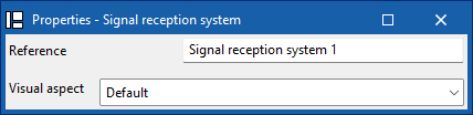
Signal reception system
Enter a signal reception into the BIM model and configure its display preferences.

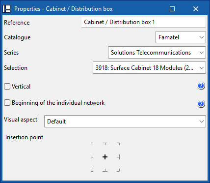
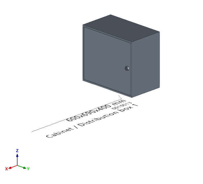
Cabinet/Distribution box
Enter a distribution cabinet or box from a manufacturer's catalogue, differentiate between the common part of the building and the private part, and set your display preferences. In addition, if the installation has several independent verticals, you can define the reference of the vertical to which this element belongs.
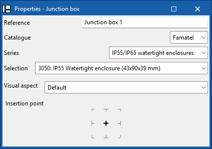
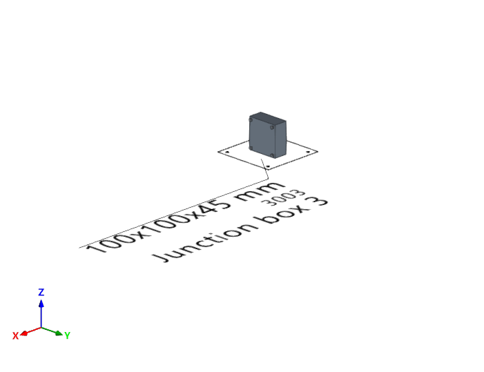
Junction box
Enter a junction box (or branch box) from a manufacturer's catalogue and set your display preferences.
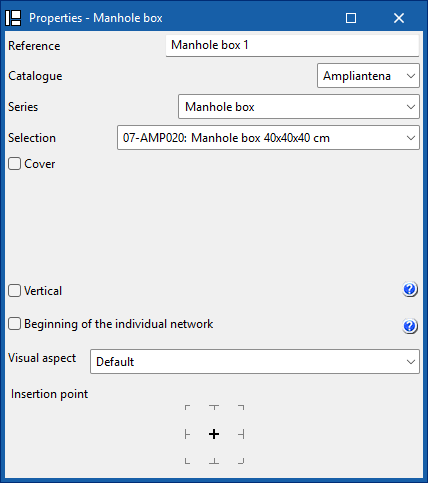
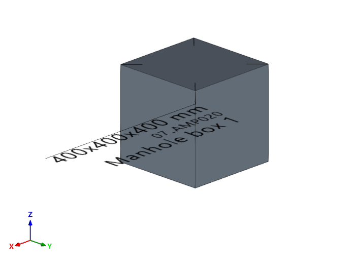
Manhole box
Enter a manhole into the BIM model from a manufacturer's catalogue, add a cover from a catalogue, and configure your display preferences. In addition, if the installation has several independent verticals, you can define the reference of the vertical to which this element belongs.
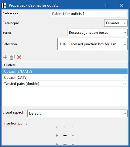
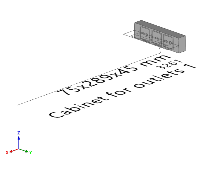
Outlet box
Enter an outlet box into the BIM model from a manufacturer's catalogue. You must indicate the socket bases and whether they are coaxial, coaxial (S/MATV), coaxial (CATV), twisted pair, twisted pair (double), fibre optic or reserve. You can also configure your display preferences.
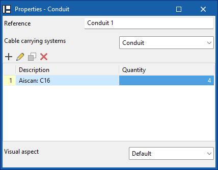
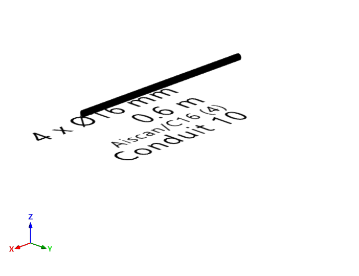
Conduit
Enter the tray, channel, or pipe type ducting from a manufacturer's catalogue, and configure your display preferences.
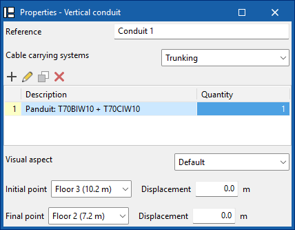
Vertical conduit
Enter tray, channel or pipe type vertical ducting from a manufacturer's catalogue, define its start and end points, and configure your display preferences.
| Note: |
|---|
| When inserting elements, references are generated sequentially, which prevents duplication both during insertion and when duplicating or creating symmetries. In addition, the insertion point functionality is included, which allows you to capture and anchor elements to architectural references for more precise placement in the model. |
| Further information: |
|---|
| The program incorporates an automatic check for repeated ID references, using an error warning, which allows duplications in model elements to be detected. It also identifies disconnected elements of the installation such as manholes, pipes, boxes or sockets, making it easier to detect inconsistencies in the design. |