Introduction
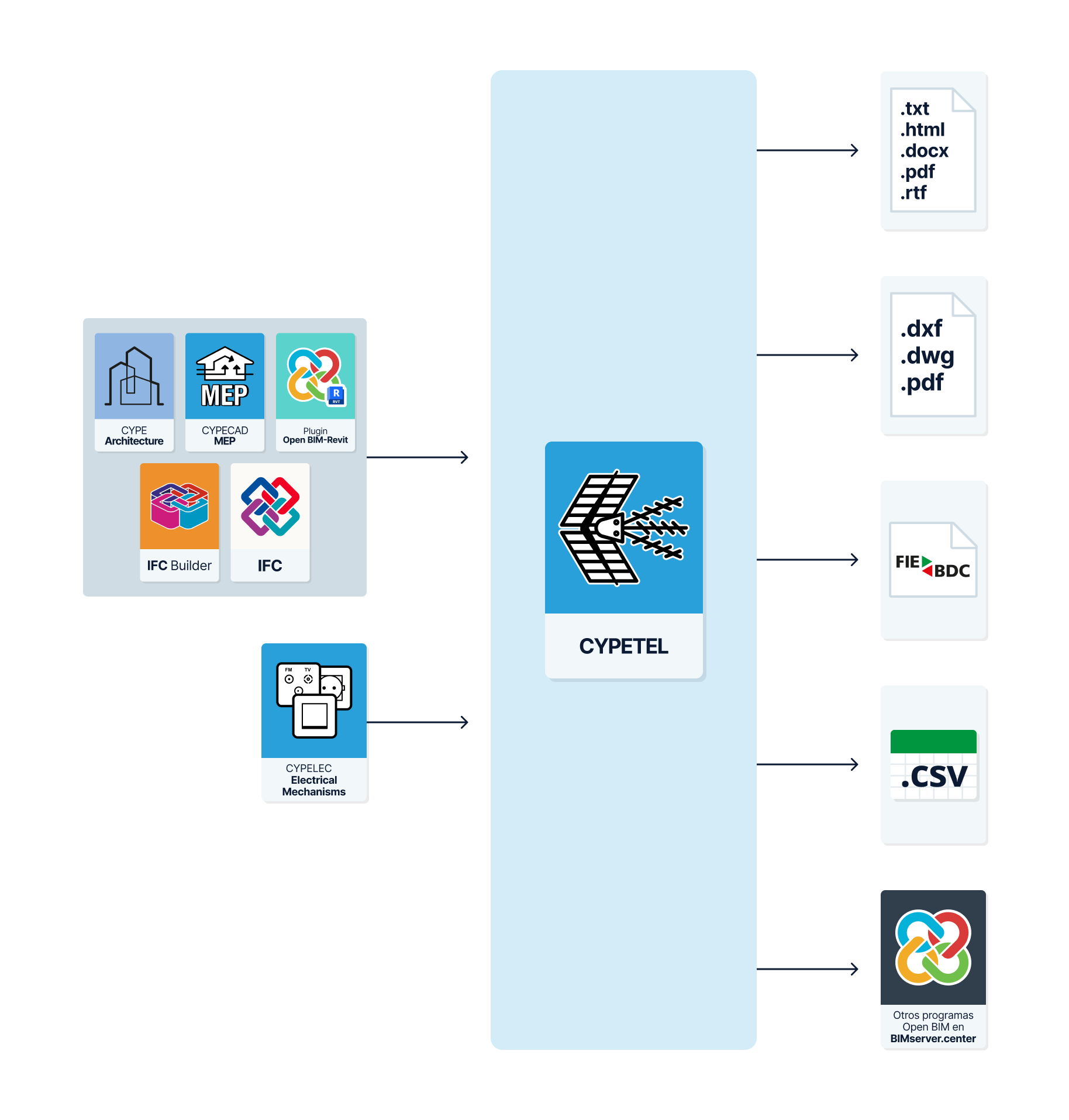
CYPETEL is a program specialising in the calculation and design of telecommunications installations based on manufacturer catalogues. It provides the tools for BIM modelling of telecommunications infrastructure and enables the design and analysis of infrastructure network diagrams and diagrams for coaxial cable networks, fibre optic cables, hybrid fibre-coaxial (HFC) networks, copper twisted-pair cables, video door entry systems and video surveillance. It also offers the ability to create detailed graphical layouts of installations to facilitate the design of racks or headends, and includes the option to generate a bill of quantities for the installation as well as the technical project documentation for the common telecommunications infrastructure (ICT).
The program enables both the design and analysis of telecommunications installations that comply with regulatory standards, based on the values and characteristics of predefined standards, and installations that do not comply with such standards, as it allows for the definition of checks.
Workflows supported by the program
As CYPETEL is an Open BIM tool and is connected to the BIMserver.center platform, it offers a range of workflow options.
Data entry
Free-form modelling/modelling using templates
- Design the installation by entering the data directly into CYPETEL.
- Design the installation in CYPETEL using DXF/DWG, DWF, or image (.jpeg, .jpg, .bmp, .wmf) templates.
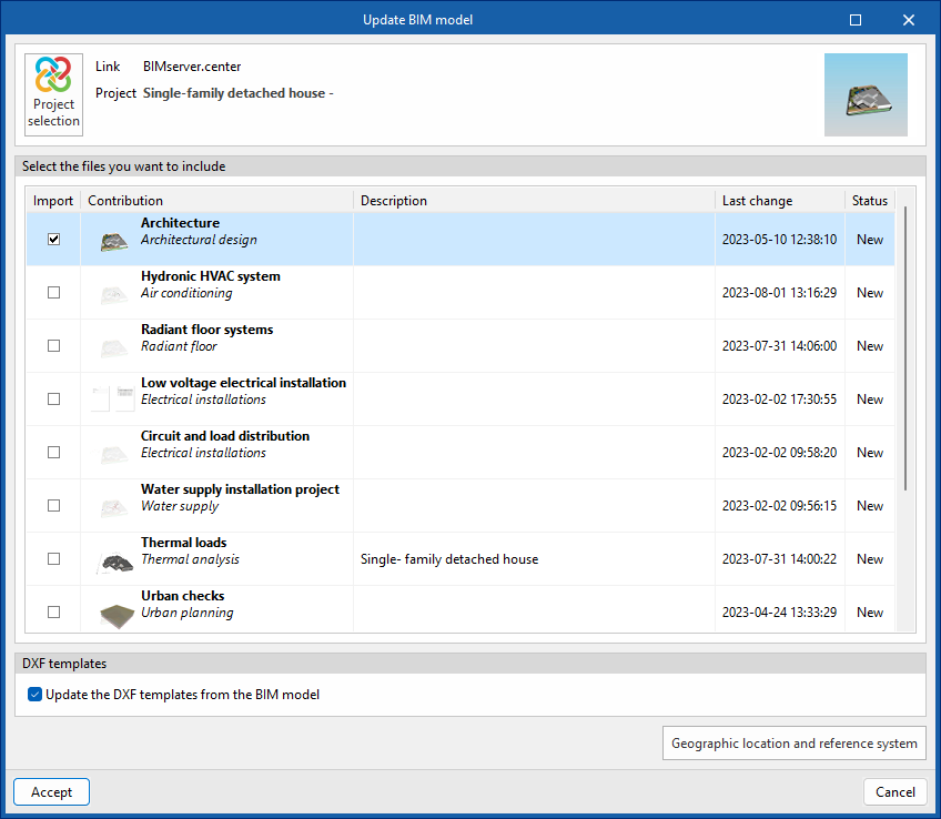
Importing BIM models
- Import a model containing a building’s geometry. This allows you to generate the building’s floor levels and floor plans and to add the installation elements based on that geometry. The available options include the following:
- Import models designed in IFC Builder.
- Import models designed in CYPE Architecture.
- Import models in IFC format (generated by CAD/BIM software such as Allplan, ArchiCAD and others) uploaded to the BIMserver.center project via the web platform.
- Import models designed in Autodesk Revit using the Open BIM - Revit plugin.
Data output
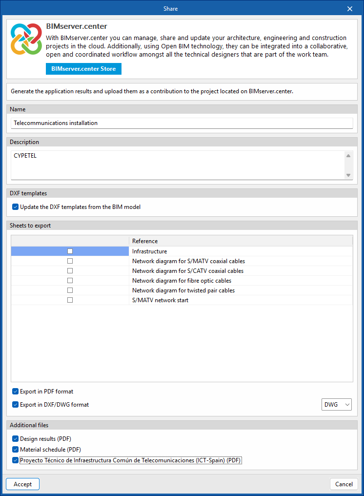
- Export lists to HTML, DOCX, PDF, RTF and TXT formats.
- Export drawings to DXF, DWG and PDF formats.
- Export the budget to FIEBDC-3, HTML, DOCX, PDF, RTF and TXT formats, as well as to CSV.
- Export of the technical project documents for the Common Telecommunications Infrastructure (ICT).
- Export data generated using CYPETEL to the BIMserver.center platform in IFC and glTF formats. This allows authorised project participants to view the data.
Sequence of data input and output for the design and analysis of telecommunications systems
Telecommunications network diagrams can be defined and calculated in the "Diagrams: Analysis" tab of the program using the following sequence of data input and output:
- Creating a new project (from "File", "New").
- (Optional) Linking to BIMserver.center and importing the levels and floor plans from the BIM model; defining the applicable codes; and importing catalogues.
- (Optional) Reviewing and configuring manufacturer's catalogues (under "Catalogues", in the "Project" section).
- Reviewing and configuring general settings: analysis options, libraries and display options (under "Settings", in the "Project" section).
- Adding telecommunications infrastructure elements to the BIM model (the "3D Model" tab, "Infrastructure" section).
- (Optional) Adding video door entry and video surveillance elements to the BIM model (the "3D Model" tab, "Video door-phone" and "Video monitoring" groups).
- Managing and generating telecommunications infrastructure diagrams (the “Diagrams: Analysis” tab, “Infrastructure” section).
- Inserting a new layout and selecting a paper size.
- Entering telecommunications infrastructure elements manually (options in the "Infrastructure" group)
- Installing collection systems, distribution cabinets/boxes, junction boxes, manholes and connection boxes, linked to the installation modelled in the BIM model.
- Inserting pipework from the manufacturer's catalogues.
- (Optional) Using editing tools to improve the visual presentation of diagrams.
- Managing and generating telecommunications network diagrams for various technologies (the "Diagrams: Analysis" tab, and the "Coaxial cable", "Fibre optic" and "Copper pairs" sections). This can be done in two ways:
- Entering the elements manually (options in the "Coaxial cable", "Fibre optic" and "Copper pairs" groups).
- Inserting a new layout and selecting a paper size.
- Network start point settings for each technology in the workspace (the "Diagrams: Analysis" tab, ‘Network start’ option).
- Adding elements to the workspace (options in the "Coaxial cable", "Fibre optic" and "Copper pairs" groups).
- (Optional) Using editing tools to improve the visual presentation of diagrams.
- Using the wizard for automatic network generation (the "Diagrams: Analysis" tab, "Network generation wizard" option).
- Entering the elements manually (options in the "Coaxial cable", "Fibre optic" and "Copper pairs" groups).
- Analysing and checking model elements and viewing of results (the "Diagrams: Analysis" tab, "Analysis" section).
- (Optional) Automatically adjusting header values (the "Diagrams: Analysis" tab, "Analysis" section).
- Managing and creating detailed diagrams of telecommunications installations, such as racks or headends (the "Diagrams: Detail" tab).
- Entering the items manually (options from the "Coaxial cable", "Fibre optic", "Copper pairs", "Mounts", "Cabinets", "Networking" and "Other" groups).
- (Optional) Using editing tools to improve the visual presentation of diagrams.
- (Optional) Managing and generating bills of quantities (the "Bills of quantities" tab).
- Viewing reports and floor plans (via the "Reports" and "Floor plans" options on the top menu bar).
- Exporting to BIMserver.center (from "BIMserver.center", "Share").
Work environment
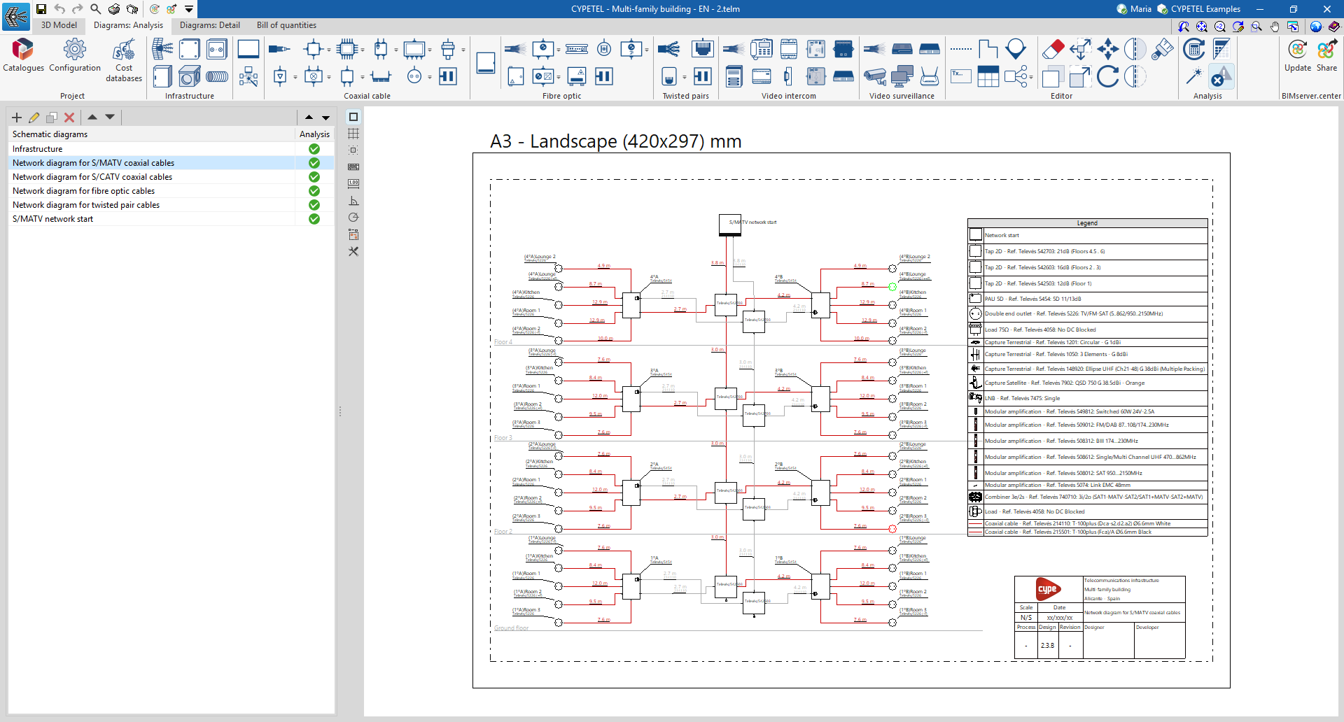
The CYPETEL workspace features four tabs with distinct working environments: "3D Model", "Diagrams: Analysis", "Diagrams: Detail" and "Bill of quantities". These environments are similar to those in other CYPE tools and feature a system of dockable windows that can be customised to adapt the workspace to the project’s requirements.
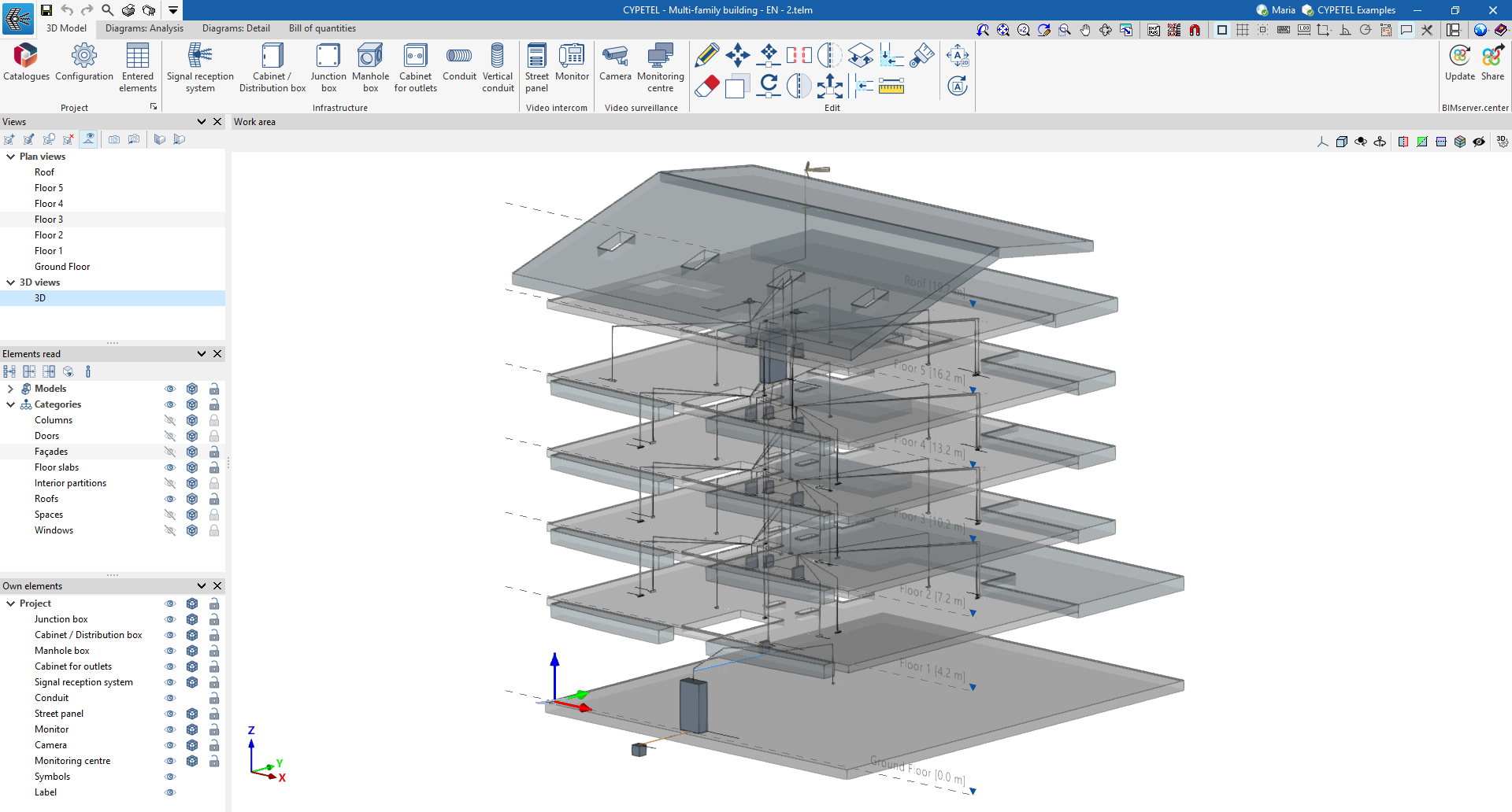
"3D Model" tab
The tab that is selected by default when the program is opened is the "3D model" tab. This tab contains the tools required to define the spatial position of telecommunications infrastructure elements (reception systems, boxes, manholes, ducts, etc.) within the BIM model via a 3D workspace. The interface displays:
- At the top, you’ll find the tools needed to manage catalogues, configure the project, and add and edit infrastructure elements.
- On the left-hand side, there are several panels containing tools for defining the project’s views and levels, as well as for managing the visibility of imported and native elements.
- The workspace is located in the centre-right of the screen and is used to enter, edit and view all elements of the infrastructure.
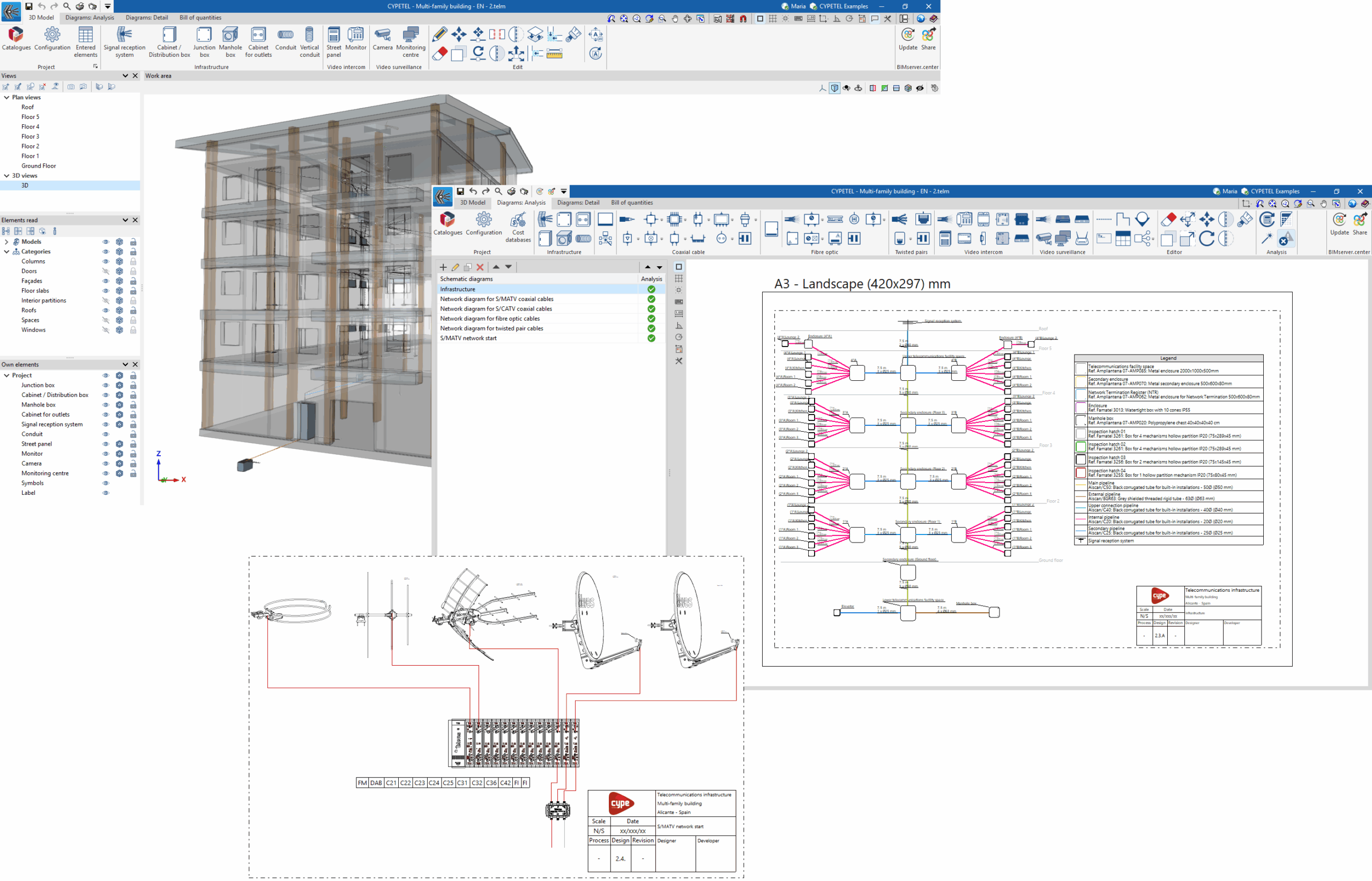
"Diagrams: Analysis" tab
The "Diagrams: Analysis" tab provides a workspace that allows you to generate diagrams of the telecommunications installation and lay them out on sheets in the desired formats. This tab displays:
- At the top, you’ll find all the tools you need to manage catalogues and configure the project; enter and edit telecommunications installation diagrams; and calculate and check the installation.
- On the left-hand side, a navigation panel for switching between the different layout options, which are composed of editable sheets with customisable dimensions and scales.
- In the centre-right of the screen is the workspace, where all the elements of the diagram are entered, edited and displayed.

"Diagrams: Detail" tab
The "Diagrams: Detail" tab differs from the previous one in terms of the tools at the top, which are focused on creating and editing graphical layouts of telecommunications installation details, such as racks or headends. The "Mounts", "Cabinets", "Networking" and "Others" sections have been added to this tab.

"Bill of quantities" tab
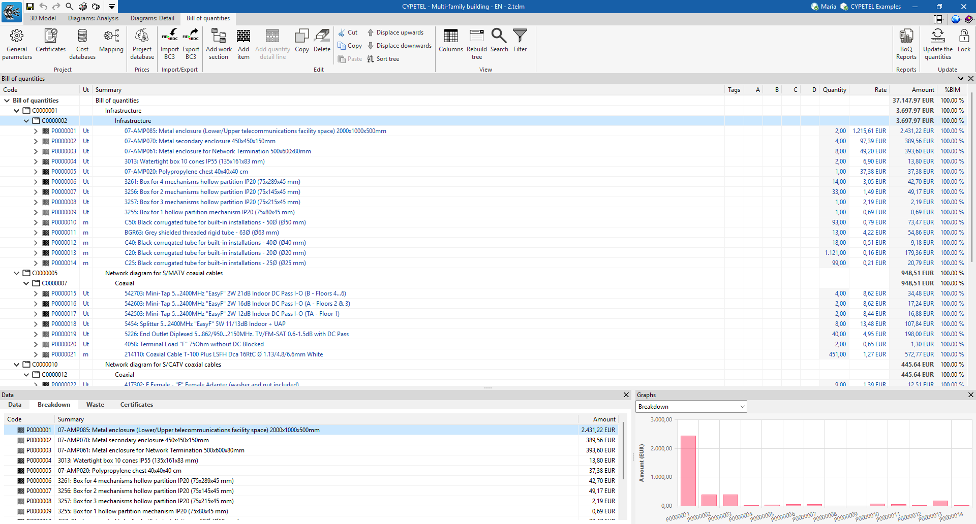
In addition, the "Bill of quantities" tab allows you to manage the bill of quantities of telecommunications installations, and displays:
- A top toolbar containing tools for creating and editing budgets, as well as tools for managing and generating lists.
- A specific section for the bill of quantities breakdown in the main body.
Setting up the working environment
When you launch the program and click on "New...", you are given the option to create a "New job", which can then be integrated into a BIMserver.center project.
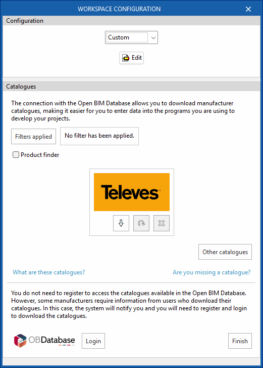
This opens the "Workspace configuration" dialogue box, which allows you to do the following:
- First, select the applicable regulations from those available in the drop-down menu. If the regulations for the desired country are not listed, you can select the "Custom" option and configure the checks to be carried out for the different networks via "Edit".
- Secondly, you can download manufacturer's catalogues, which makes data entry easier. Using the "Applied filters" and "Product search" options, you can apply filters when searching through the catalogues.
- Thirdly, at the bottom of this dialogue box, log in using your Open BIM Database username and password.
If you close or cancel this window without clicking "Finish", the program will create the project without applying any settings.
If you wish to load the settings at a later date, customise them, or manage the project catalogues, you can use the "Settings" and "Catalogues" tools respectively, located on the top toolbar of the "3D Model", "Diagrams: Analysis" and "Diagrams: Detail" tabs within the "Project" section.
| Note: |
|---|
| Please click on the following link to view the codes implemented in the program. |
Manufacturer catalogue management
The "Project" panel is located on the main toolbar of the "3D Model", "Diagrams: Analysis" and "Diagrams: Detail" tabs. From this panel, you can access "Catalogues".


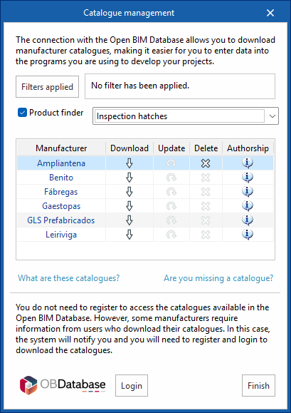
Catalogues
Using the "Catalogues" tool, you can:
- Manage manufacturer catalogues to facilitate data entry into the project.
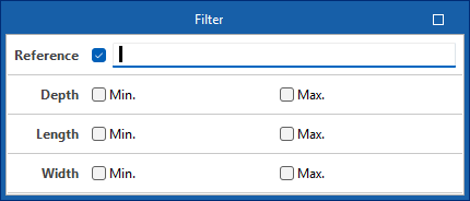
- Using the "Applied filters" option, you can apply filters to your catalogue search by category, language or country.
- Using the "Product finder" option, you can filter by dimensions and product code for infrastructure components (cabinets/distribution boxes, junction boxes or manholes) or by product type and product code for telecommunications network equipment.
- From the "Other catalogues" option, you can download, update or delete the catalogues included in the program.
- Log in to the Open BIM Database to download and use, free of charge, information on manufacturers’ products available through the software connected to this database.
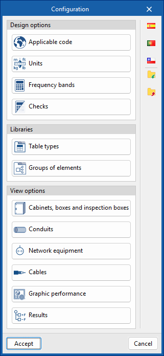
Defining the general project settings
The "Project" panel is located on the main toolbar of the "3D model", "Diagrams: Analysis" and "Diagrams: Detail" tabs. From this panel, you can define the general project options:


Configuration
From the "Configuration" dialogue box, you can load a predefined configuration (using the options on the right) and/or customise it.
The options available in this dialogue box are:
- Design options
- Applicable code
Selects the codes—from those included in the program—that affect the filtering of product selections and the generation of project lists. As it is linked to the country of application, it also determines the available channels, standards and pricing options, adapting the program’s content to local conditions. - Units
Configures the units, labels and number of decimal places for each of the quantities relating to the telecommunications installation.
If you use the "Import one of the predefined unit systems" option, available on the right-hand side of the panel, you can import one of the following unit systems:- International System
Imports units from the International System. - I-P System
Imports units from the I-P (Inch-Pound) system or the imperial system.
- International System
- Frequency bands
Sets the operating band limits, the lower frequency (MHz) and the upper frequency (MHz) for MATV, SMATV and CATV. - Checks
Configures the checks to be carried out for different telecommunications networks (coaxial cable, fibre optic and twisted-pair copper).- For coaxial cable networks, the following parameters can be tested: "Attenuation", "Power", "Carrier-to-noise ratio", "Intermodulation ratio", "Slope" and "Length".
- For fibre-optic networks: "Attenuation" and "Length".
- For copper twisted-pair networks: "Attenuation" and "Length".
- Applicable code
- Libraries
- Table types
Manages the captions or tables added to the diagrams using the "Add table" option in the "Edit" group on the main toolbar, in both the "Diagrams: Analysis" and "Diagrams: Detail" tabs. - Groups of elements
Manages the element groups created in the workspace using the "Groups of elements" option in the "Edit" group on the main toolbar, in both the "Diagrams: Analysis" and "Diagrams: Detail" tabs.
- Table types
- Display options
- Cabinets, boxes and inspection boxes
Configures the graphical representation of these elements, both on screen and on drawings. You can adjust the colour of the equipment, the visible information label, and the display or size of the reference, the catalogue/selection and the dimensions. Furthermore, it is possible to define different styles for each type of element. - Conduits
Configures the graphical representation of pipes, both on screen and on drawings. You can adjust their colour and thickness, the visible information label, and the display or size of the reference, length, catalogue/selection and dimensions. Furthermore, it is possible to define different styles for each type of pipe. - Network equipment
Configures the graphical representation of these elements, both on screen and on drawings. You can adjust the colour of the equipment, the visible information label, and the display or size of the reference and catalogue/selection. Furthermore, it is possible to define different styles for each type of equipment. - Cables
Configures the graphical representation of cables, both on screen and in drawings. You can adjust their colour and thickness, the visible information label, and the display or design of the reference, the length, and the catalogue/selection. Furthermore, it is possible to define different styles for each type of cable.
- Graphic performance
Choose whether the elements in the "Diagrams: Detail" tab are displayed in detail—i.e., at their original resolution—or in a simplified form, which will speed up the program’s performance. You can also set the visibility of the tables, choosing either "Always visible" or "Visible only when displaying results".
- Results
Configures the graphical representation of the most favourable and least favourable elements in the analysis results for telecommunications installation diagrams, by defining their colours and symbols.
- Cabinets, boxes and inspection boxes
Entering infrastructure elements into the BIM model
The main toolbar of the "3D Model" tab contains the "Infrastructure" group, which provides the tools needed to define the spatial position of telecommunications infrastructure elements in the BIM model through a 3D working environment. From this group, you can add the following elements to the installation:

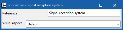
Signal reception system
Enter a signal reception into the BIM model and configure its display preferences.

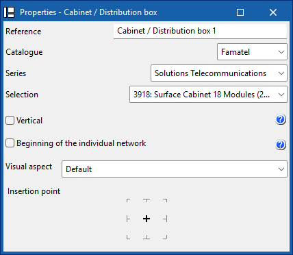
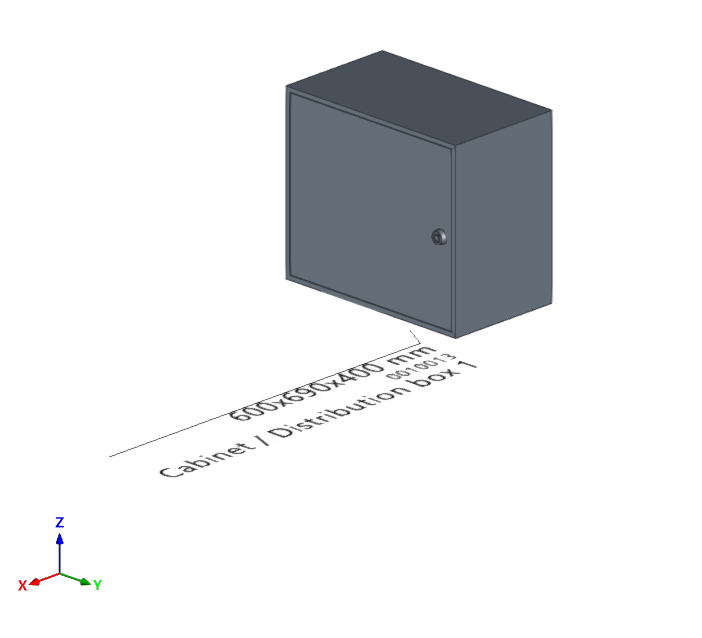
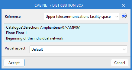
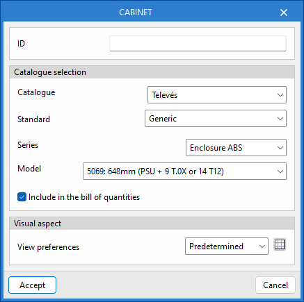
Cabinet/Distribution box
Enter a distribution cabinet or box from a manufacturer's catalogue, differentiate between the common part of the building and the private part, and set your display preferences. In addition, if the installation has several independent verticals, you can define the reference of the vertical to which this element belongs.
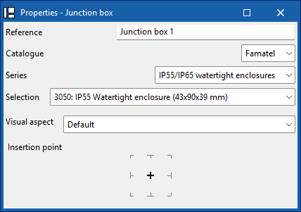
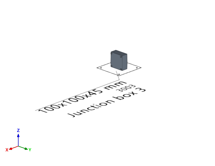
Junction box
Enter a junction box (or branch box) from a manufacturer's catalogue and set your display preferences.
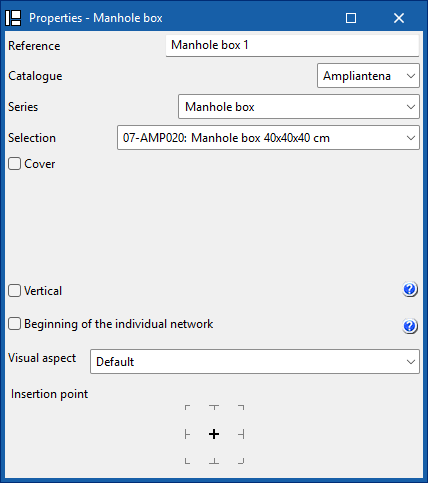
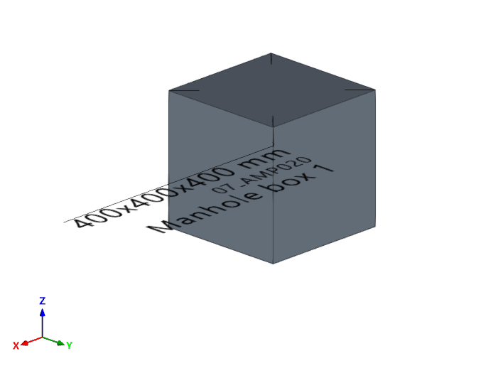
Manhole box
Enter a manhole into the BIM model from a manufacturer's catalogue, add a cover from a catalogue, and configure your display preferences. In addition, if the installation has several independent verticals, you can define the reference of the vertical to which this element belongs.
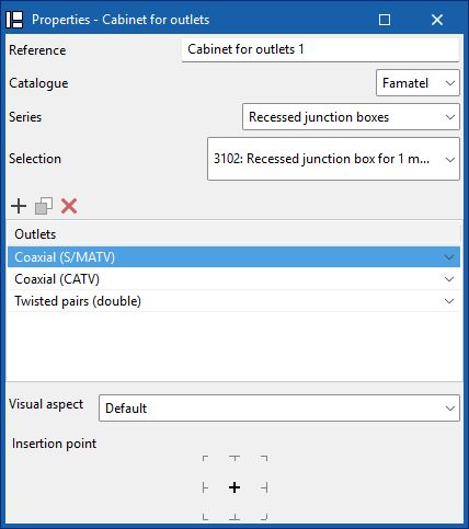
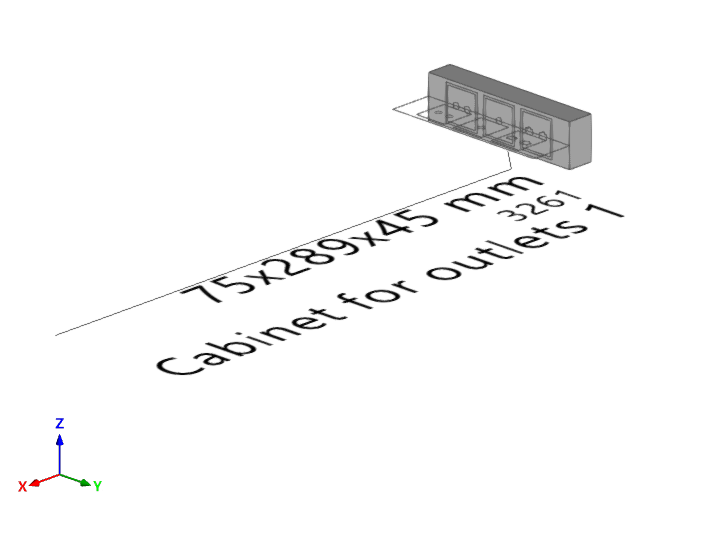
Cabinet for outlets
Enter a cabinet for outlets into the BIM model from a manufacturer's catalogue. You must indicate the socket bases and whether they are coaxial, coaxial (S/MATV), coaxial (CATV), twisted pair, twisted pair (double), fibre optic or reserve. You can also configure your display preferences.
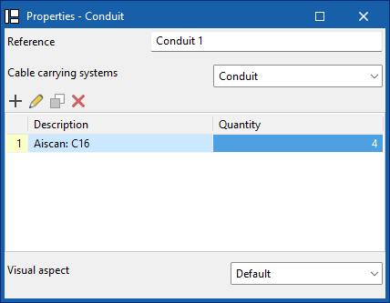
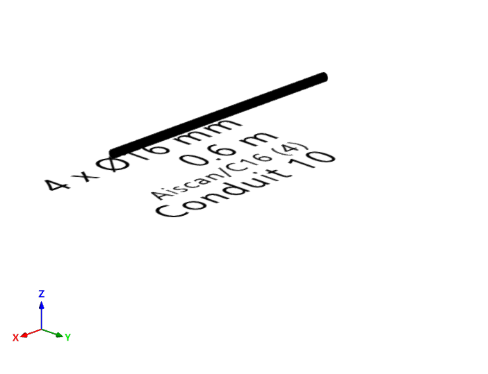
Conduit
Enter the tray, channel, or pipe type ducting from a manufacturer's catalogue, and configure your display preferences.
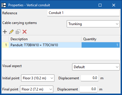
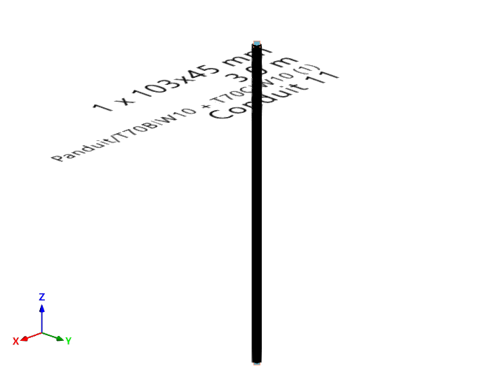
Vertical conduit
Enter tray, channel or pipe type vertical ducting from a manufacturer's catalogue, define its start and end points, and configure your display preferences.
| Note: |
|---|
| When inserting elements, references are generated sequentially, which prevents duplication both during insertion and when duplicating or creating symmetries. In addition, the insertion point functionality is included, which allows you to capture and anchor elements to architectural references for more precise placement in the model. |
| Further information: |
|---|
| The program incorporates an automatic check for repeated ID references, using an error warning, which allows duplications in model elements to be detected. It also identifies disconnected elements of the installation such as manholes, pipes, boxes or sockets, making it easier to detect inconsistencies in the design. |
Managing the elements added to the project
In the "Project" section of the main toolbar on the "3D model" tab, you will find the option to manage the elements added to the project:

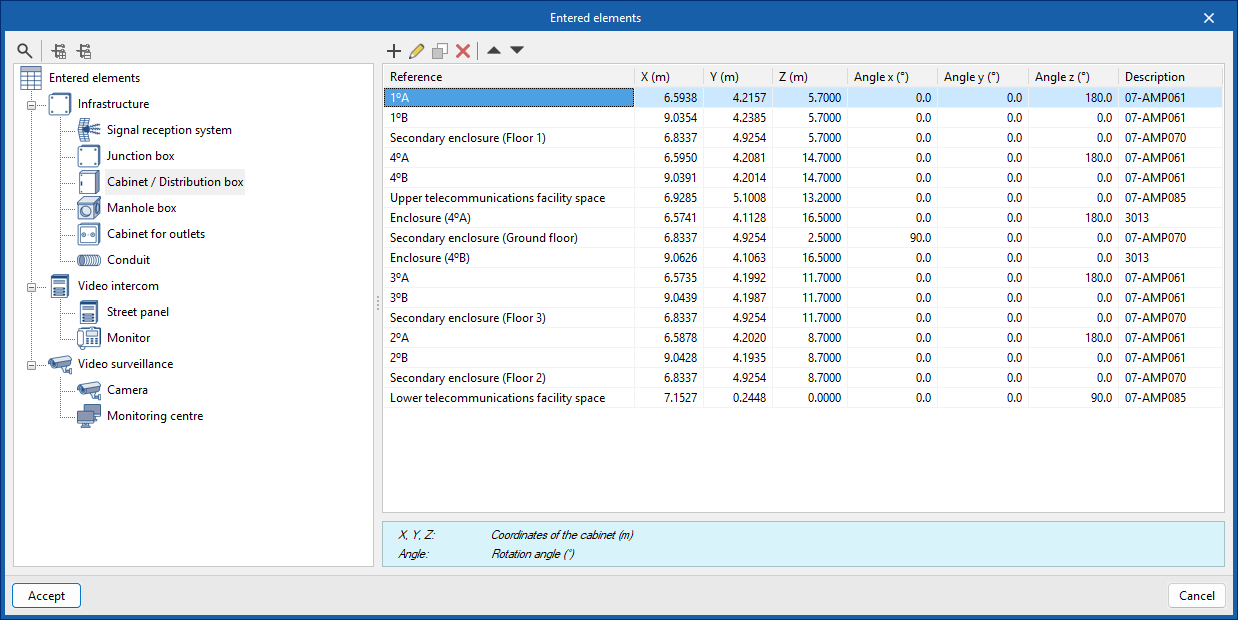
Elements entered
This can be used to view the details of each of the installation components included in the model, such as their reference number, position and description, in the following tables:
- Infrastructure
- Signal reception system
- Junction box
- Cabinet / Distribution box
- Manhole
- Cabinet for outlets
- Conduits
- Video intercom
- Street panel
- Monitor
- Video surveillance
- Camera
- Monitoring centre
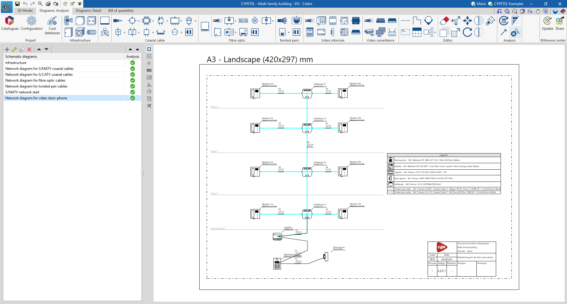
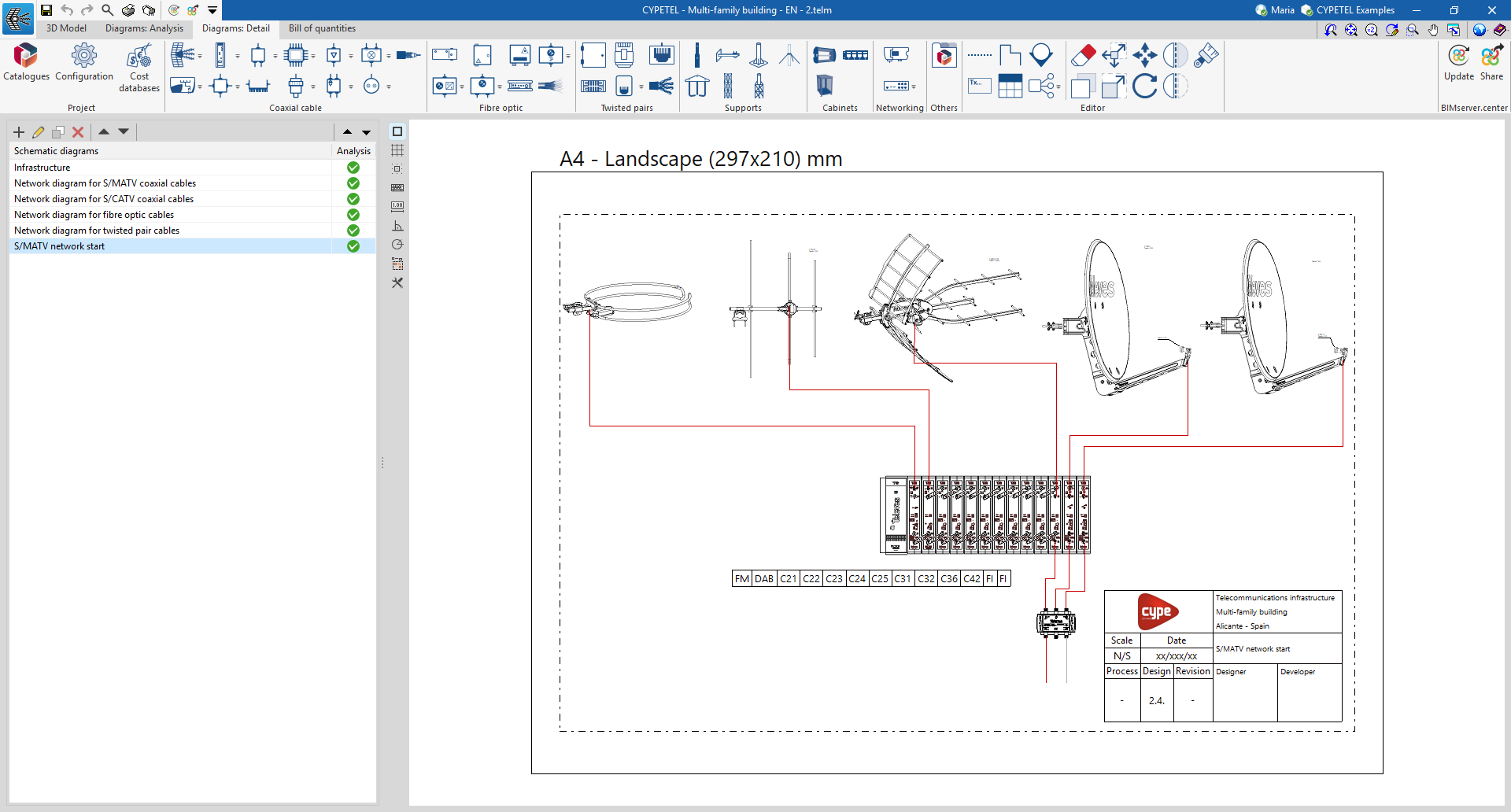
Management and creation of schematic diagrams
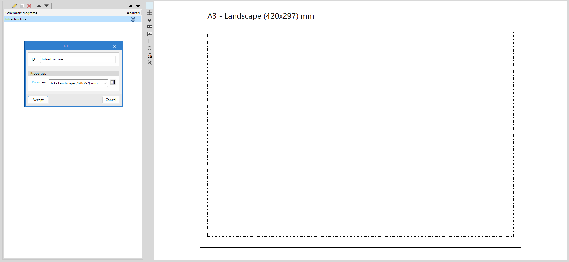
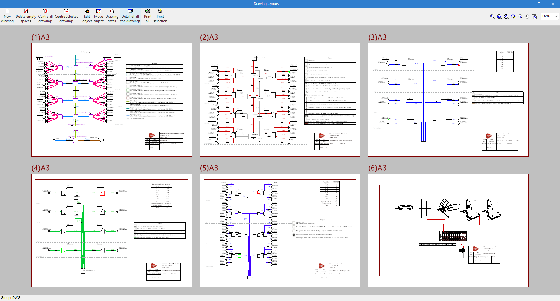
Telecommunications diagrams are composed of sheets in various formats. The tools for creating and managing diagrams are located on the left-hand side of the interface, under the "Diagrams: Analysis" and "Diagrams: Detail" tabs.
When creating or editing a layout, you must enter an identifier and select the paper size. The available paper sizes can be configured via the "Page size" option, specifying a reference, its dimensions and margins, as well as the colours of the paper and the margin and reference lines.
Entering infrastructure elements into the diagram
The "Diagrams: Analysis" tab can manually generate telecommunications infrastructure diagrams based on the information from the model developed in the "3D Model" tab, using the available drawing tools:
- To compose the diagrams from scratch, first create the sheets of the necessary formats using the options on the left side. Then, insert the diagram elements into the work area on the right side using the options in the top toolbar.
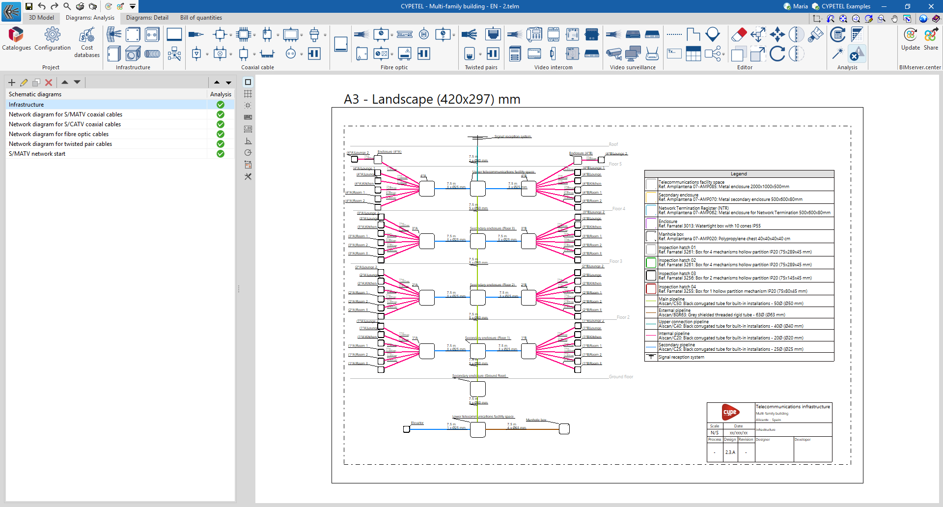
Within the "Diagrams: Analysis" tab, in the "Infrastructure" group of the main toolbar, you will find the options that allow you to insert the elements of the telecommunications infrastructure:

- Signal reception system*
- Cabinet / Distribution box*
- Junction box*
- Manhole box*
- Outlet box*
- Conduit
*The data for these infrastructure elements can be linked to the 3D model using the selection list and disappear once they have been entered.
In the case of conduits, the link to the elements of the 3D model is made automatically, as it analyses the connections between elements in the diagram.
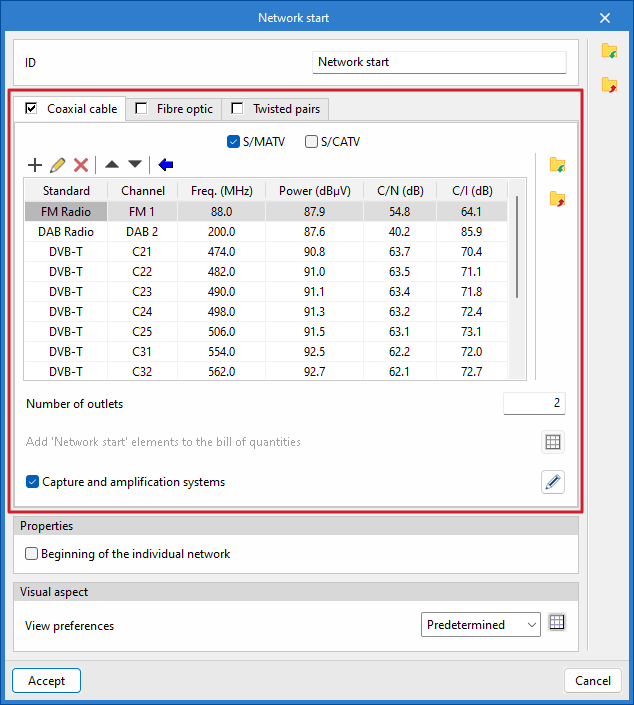
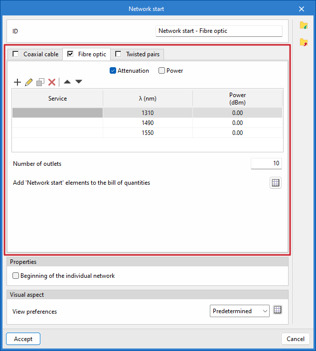
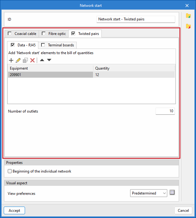
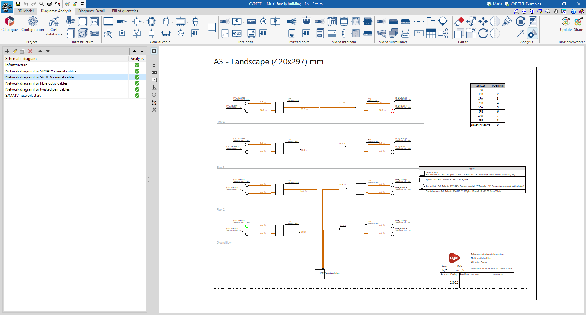
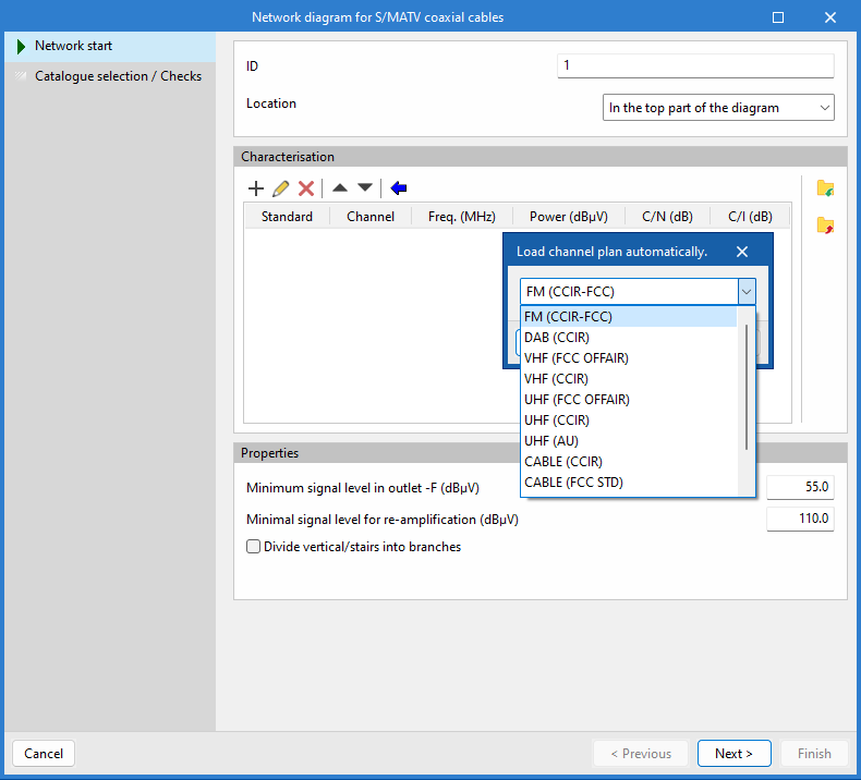
Network start
Next to the "Infrastructure" section of the main toolbar on the "Diagrams: Analysis" tab is the "Network start" option. This tool acts as the network header for any telecommunications technology: coaxial cable, fibre optic or copper pairs.

In the "Network start" dialogue box, you must enter the following parameters:
- ID
Allows you to assign a name to the diagram. - "Coaxial cable" tab
Defines the headend of a coaxial cable network.- S/MATV / S/CATV
Selects whether the network will be of the "S/MATV" type (terrestrial and satellite signal reception system), "S/CATV" type (broadband system using coaxial cable), or both. - Add
Adds new channels to the list, specifying the standard, the channel (frequency band and specific frequency), the power, the carrier-to-noise ratio and the carrier intermodulation level. Once the channels have been added to the list, you can edit, delete or move the selected item in the list. - Automatic channel list update
Automatically adds new channels to the list by selecting from predefined options based on the transmission standard. - Number of outlets
Specifies the number of outputs that the network node will have in the diagram. - Add 'Network start' elements to the bill of quantities
This option is only enabled if "S/CATV" is selected, and allows you to add elements that will subsequently be included in the project bill of quantities and the materials table. - Capture and amplification systems
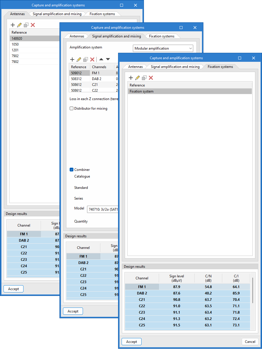
Defines a pickup and amplification system and, depending on the system selected, updates the channel list with the calculated values. From the dialogue box that opens with the same name, you can access the following tabs:- Antennas
Adds antennas, specifying their type, the repeater (optional) they are aimed at, the channels they receive, and the cable connecting them to the amplification system. - Signal amplification and mixing
Choose between the different amplification systems – "Modular amplifier", "Broadband amplifier" or "Amplifier unit" – define channels and other parameters, such as the gain value or losses in each Z connection, and configure connections for mixing terrestrial and satellite signals. - Fixation systems
Configures antenna mounting systems, specifying the wind speed and antenna locations to calculate the resulting moment. It also indicates whether a mast base, turret, wind brace, or other mounting is used.
- Antennas
- S/MATV / S/CATV
| Note: |
|---|
| You can use the following equivalents to identify the names of coaxial cable networks by analogy with those specified in Spanish regulations: S/MATV (Single Master TV Antenna) = RTV (Terrestrial and Satellite Radio and Television Services) S/CATV (Single Community Antenna Television) = TBA Coaxial (Broadband Telecommunications) |
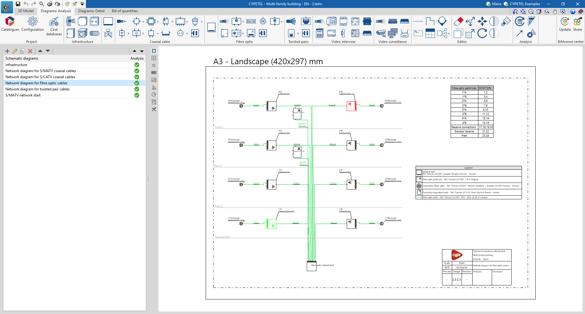
- "Fibre optic" tab
Defines the headend of a fibre-optic cable network or a hybrid fibre-coaxial (HFC) network.- Attenuation / Power
Choose between an "Attenuation" network (broadband networks) or a "Power" network (HFC networks). - Add
Adds new services to the list by specifying the wavelengths and power levels. Once the services have been added to the list, you can edit, copy, delete or move the selected item from the list. - Number of outlets
Specifies the number of outlets that the network node will have in the diagram. - Add 'Network start' elements to the bill of quantities
This option is only enabled if 'Attenuation' is selected, and allows you to add elements that will subsequently be included in the project quote and the materials schedule. - Frequency plan
This option is only enabled if "Power" is selected, and allows you to set a frequency plan for the calculation.
- Attenuation / Power
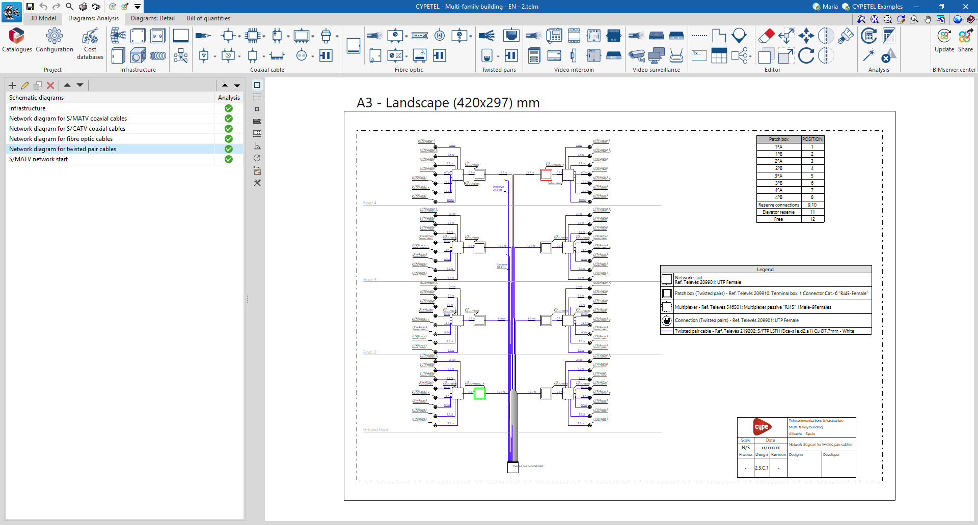
- "Copper pairs" tab
Defines the header for a copper-pair cable network.- Data - RJ45 / Patch panels
Includes elements in the network header: "Data - RJ45", "Patch panels" or both. - Add
Adds new "Network Start" elements to the bill of quantities by selecting them from the catalogue and specifying the quantity. Once the equipment has been added to the list, you can edit, copy, delete or move the selected item from the list. - Number of outlets
Specifies the number of outlets that the network node will have in the diagram.
- Data - RJ45 / Patch panels
- Start of the individual network
This allows the common areas of the building to be distinguished from the private areas. - Display preferences
Selects the display style in the diagram.
Once the network start point for the selected telecommunications technology has been defined, click "Accept", and it will be placed on the diagram.
Inserting telecommunications network elements into the diagram
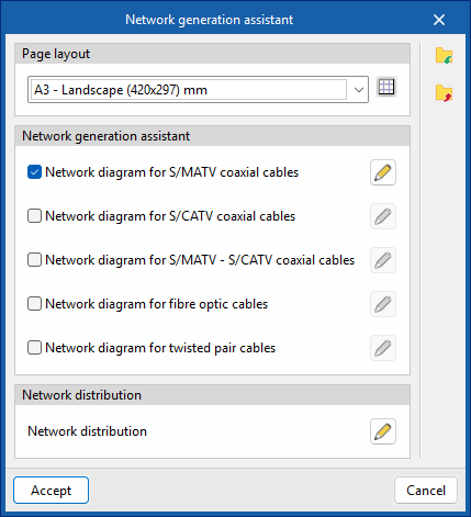
The "Diagrams: Analysis" tab allows you to automatically generate telecommunications network diagrams based on the information provided via a wizard, or to create them manually using the available drawing tools:
- To create diagrams from scratch, you first create the slides in the required formats using the options on the left-hand side. You then add the diagram elements to the workspace on the right-hand side using the options on the top toolbar.
- To generate the diagrams automatically, use the "Network generation assistant" option at the top. The user is then free to modify the generated diagrams on the workspace using the options on the top toolbar.
Manual installation of telecommunications network components
Within the "Diagrams: Analysis" tab, in the "Coaxial cable", "Fibre optic" and "Twisted pairs" sections of the main toolbar, you will find the options for entering telecommunications network elements:

These groups enable the creation of distribution networks for the various technologies covered by the program (coaxial cable networks, fibre-optic networks, hybrid fibre-coaxial [HFC] networks and copper pair networks).
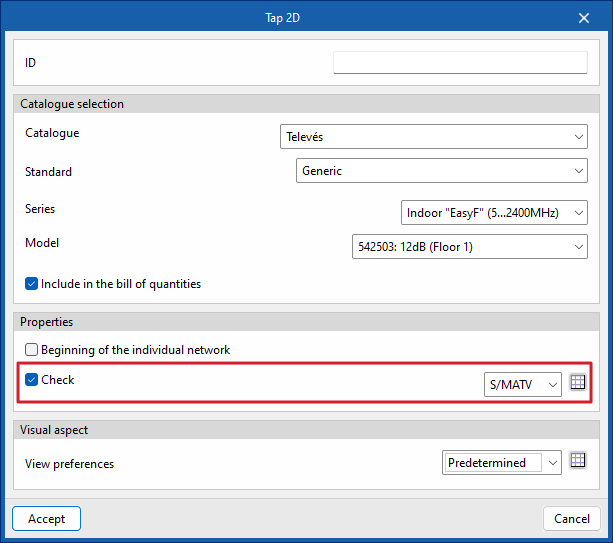
The program includes a wizard for importing the regulatory checks mentioned in the "Settings" section or for customising regulatory limits. Checks can be assigned to any piece of equipment using the available options by ticking the "Check" box, which appears in the dialogue box for the selected equipment.
| Best practice: |
|---|
| The program uses alerts to flag regulatory non-compliance or incorrectly configured installations, to help ensure they are set up correctly. |
Coaxial cable
From the "Coaxial cable" section, you can add the following elements to the installation:
- Coaxial cable
- Taps
- Multiswitch
- PAU
- ATI
- Fittings
- Line amplifiers
- Mixers
- Splitters
- Multi ATE ATI
- Outlets
Fibre optic
From the "Fibre optic" section, you can add the following elements to the installation:
- Fibre-optic cable
- Splitters
- ONT
- Outlets
- Fittings
- Secondary enclosure
- Optical / Coaxial converters
- Fibre-optic PAU
Twisted pair
From the "Twisted pair" section, you can add the following components to the installation:
- Copper twisted-pair cable
- Outlets
- PAU / Multiplexer
Automated tool for generating telecommunications networks

The program features a wizard for creating diagrams quickly that streamlines the design process by significantly reducing the time spent on manual modeling. It also facilitates regulatory compliance and minimizes errors, providing an efficient solution for creating telecommunications network diagrams.
| More information: |
|---|
| The settings configured in the wizard are retained for the project when the program is closed. Furthermore, they can be imported and exported to files on the hard drive via the options in the right-hand column, allowing them to be reused in other projects. |
Incorporation of video door entry and video surveillance systems into the layout
Under the "Diagrams: Analysis" tab, in the "Video intercom" and "Video surveillance" sections of the main toolbar, you will find the options for adding equipment to design video doorphone and CCTV diagrams:

Video doorphone
From the "Video intercom" section, you can add the following elements to the installation:
- Cable
- Monitor
- Power line adapter
- Relay
- Distributor
- Street panel
- Supplier
- Door opener
- Line amplifier
- Switch
Video surveillance
From the "Video surveillance" section, you can add the following elements to the installation:
- Cable
- Video recorder
- Switch
- Camera
- Monitoring centre
- Router
Editing tools
The "Edit" section of the main toolbar on the "3D Model", "Diagrams: Analysis" and "Diagrams: Detail" tabs contains the following tools:


Editing
The options in this section allow you to perform the following editing operations on the installation elements entered in the model and the diagram:
| Edit | Edits the parametric properties of the selected element in the model. | |
 | Move a group | Moves a group of items. |
| Move item | Moves an element or a node within an element. | |
 | Divide | Splits an element in two at the selected point. |
 | Symmetry (move) | Moves a selection of elements symmetrically about a vertical plane defined by two points. |
 | Copy to another floor plan | Copies a selection of elements to another floor plan. This feature is only available in floor plans. |
 | Extend/truncate to intersection | Extends or trims two selected elements to their point of intersection. |
 | Equalise | Assigns the properties of one drawing resource to others. When you select a drawing resource, any resources with the same properties are highlighted in orange. |
 | Delete | Deletes a previously entered item. |
 | Copy | Create a copy of one or more items. |
| Turn | Rotates an object around the "x", "y" or "z" axes. | |
 | Symmetry (mirror) | Copies a selection of elements that are symmetrical about a vertical plane defined by two points. |
| Adjust height | Adjusts the vertical position of a selection of elements. | |
 | Extend/trim element | Extends or trims an element relative to a reference element. The first element serves as the reference, whilst the second is extended or trimmed after applying the option. |
| Measuring lengths on a plane | Measures distances and angles between points defined in the model. If a closed contour is selected, it also calculates the area. | |
 | Geometric transformations | Edits the size, position or label, or rotates an existing element. |
 | Increase/decrease the size of a group | Changes the size of a group of elements. |
 | Rotate a group | Breaks up a group of elements. |
Label
The options in this section allow you to perform the following operations on the labels of the installation elements entered in the model:
| Move label in 2D mode | Moves the selected label on the element's plan view. | |
| Rotate label | Turn the label to face the correct way. |
Notes
The options in this section allow you to insert the following drawing elements into the installation diagrams:
Reference line
Enters a reference line that can be used to indicate the layout of the scheme’s elements on the different floors of the building.
Polyline
Inserts a polyline using points, either continuous or broken, specifying its colour and line weight.
Add a continuation point
Inserts a continuation point by selecting one previously defined in "Settings" or by creating a new one and customising its appearance (colour, ID, type, etc.).
Text
Inserts a text box that is left-aligned, right-aligned or centred, with horizontal or vertical text flow. You can specify the text colour and size, as well as the border and background fill properties.
Table types
Insert captions or tables containing additional information into the diagrams. When creating a table, it can be of the "Generic" type, in which case you specify the number of rows and columns and fill in the cell contents using a free-form editor; or of the "Caption" type, in which case it can be "Automatically generated" based on the elements arranged in the diagram. Table types can also be managed using the relevant option under “Settings”.
Groups of elements
Create or insert groups of elements in the workspace using the "Groups of elements" option in the "Edit" block on the main toolbar, in both the "Diagrams: Analysis" and "Diagrams: Detail" tabs. Groups of elements can also be managed using the relevant option in "Settings".
In addition, the "Edit" section of the main toolbar on the "3D model" tab contains the following tools:
Managing the visibility of project elements
The visibility of the various elements required to model the project can be managed via the following sections:
- Views
Using this option, you can create, edit and save the opening scene, as well as return to it. - Levels
Makes it easier to link model elements to various views, such as building floor plans or other reference drawings. - Imported elements
These are elements exported from other disciplines. - Own elements
These are the elements created in the program itself.
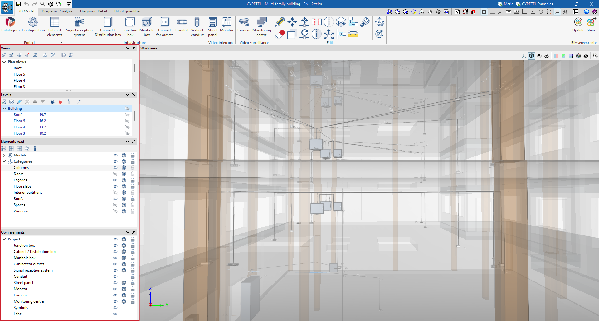
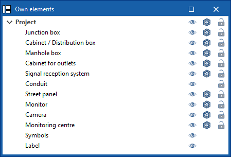
Managing own elements
Within the "Project elements" section, project elements are organised into layers. These layers correspond to the infrastructure, video intercom and video surveillance elements that can be incorporated into the 3D model. In addition, the "Symbols" and "Label" layers are included, allowing you to quickly enable or disable the visibility of these elements.
The following buttons are displayed next to each component in the tree:
- Visible
Enables or disables the visibility of elements. - Display mode
Choose between normal, transparent and wireframe display modes. - Capture
Enables or disables object references for elements.
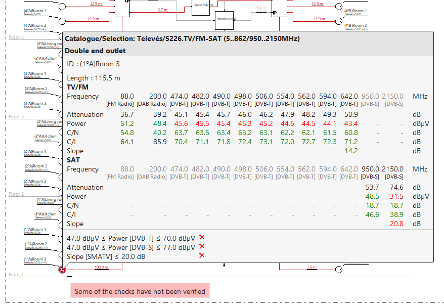
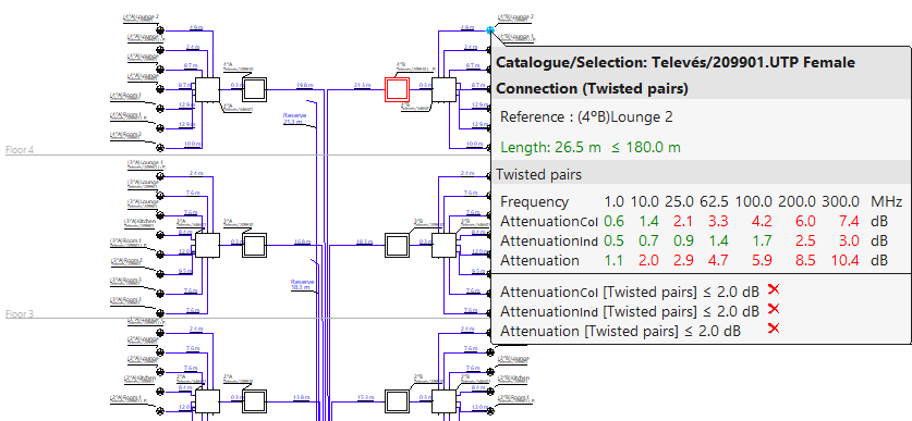
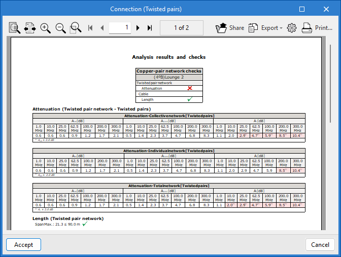
Analysing and checking the telecommunications installation
In the "Analysis" group of the main toolbar of the "Diagrams: Analysis" tab, you can access the following tools:

Update results
This option can analyse the installation and check whether the parameters calculated in the telecommunications installation elements are within the permitted ranges, based on the configuration defined in the "Configuration" section of the "Project" group.
The result is a direct display with error or warning messages about the elements that present a problem in the check, as well as a detailed report if the "Consult results" tool is used on each element.
In turn, the "Update results" option can detect issues related to the consistency between the design made in the "3D model" tab and the elements entered in the infrastructure network diagram. This tool facilitates the detection of duplicates, the updating of conduit lengths and the selection of products, thus ensuring correlation with the 3D model and helping to complete the installation diagram.
View results
This option allows you to view the checks for elements where the "Check" option has previously been assigned.
After analysing and activating the "View results" tool, from the diagram and by hovering over the element, it is possible to view the checks that have been carried out. Checks that do not comply are highlighted in red, and those that do comply are highlighted in green.
In addition, when you click on the element, a detailed list of the checks performed appears.
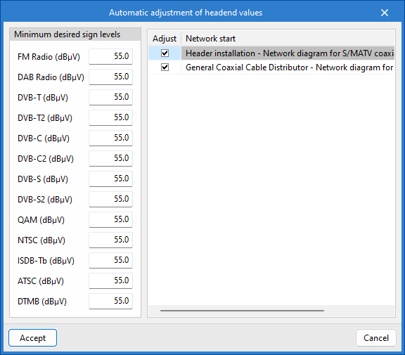
Automatic adjustment of headend values
This tool can modify the signal levels of the channels at the "Network start". It also adjusts the gain of the headend amplifiers of the reception and amplification system to meet the requirements of the network start.
Show/hide incidents
When this option is enabled, elements of the installation that have warnings or errors—whether during entry, editing, or analysis checks, or due to issues resulting from an incorrect design or potential regulatory non-compliance—are highlighted. When you hover the cursor over each issue, a descriptive message appears with details about the warning or error.
Inserting elements for graphical layouts of installation details
The "Diagrams: Detail" tab allows you to manually generate detailed diagrams of the telecommunications installation using the available drawing tools:
- To create diagrams from scratch, you first create the pages in the required formats using the options on the left-hand side. You then add the diagram elements to the workspace on the right-hand side using the options on the top toolbar.
The main toolbar on the "Diagrams: Detail" tab contains a range of elements for creating graphical layouts of telecommunications installation details, enabling the design of racks or headends. These elements are divided into the following groups:

Coaxial cable
From the "Coaxial cable" section, you can add the following elements to the installation:
- Collection system
- Processing headends
- Delivery drivers
- Multiswitch
- Line amplifiers
- Mixers
- Coaxial cable
- Headend amplification
- Taps
- Multi ATE ATI
- Fittings
- PAU
- Outlets
Optical fibre
From the "Fibre optics" section, you can add the following elements to the installation:
- Main fibre-optic register
- Secondary register
- Fibre-optic PAU
- Fittings
- Optical / Coaxial converters
- Splitters
- ONT
- Fibre-optic cable
Twisted pairs
From the "Twisted pairs" section, you can add the following elements to the installation:
- Main terminal enclosure/panel
- Connectors
- Outlets
- Power strip
- PAU / Multiplexer
- Twisted pair cable
Supports
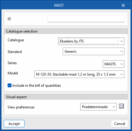
From the "Supports" section, you can add the following elements to the installation:
- Mast
- Mast support
- Antenna support
- Wind kit
- Base (Tower)
- Bottom/intermediate span (Tower)
- Top span (Tower)
Cabinets
From the "Cabinets" section, you can add the following elements to the installation:
- Chest
- 19-inch panel
- 19-inch rack
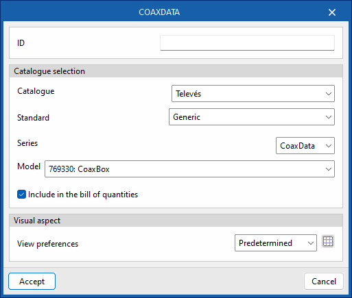
Networking
From the "Networking" section, you can add the following elements to the installation:
- CoaxDATA
- FibreData GPON
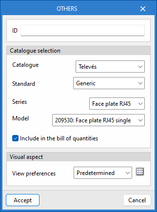
Others
From the "Others" section, you can add other elements from the catalogues to the installation.
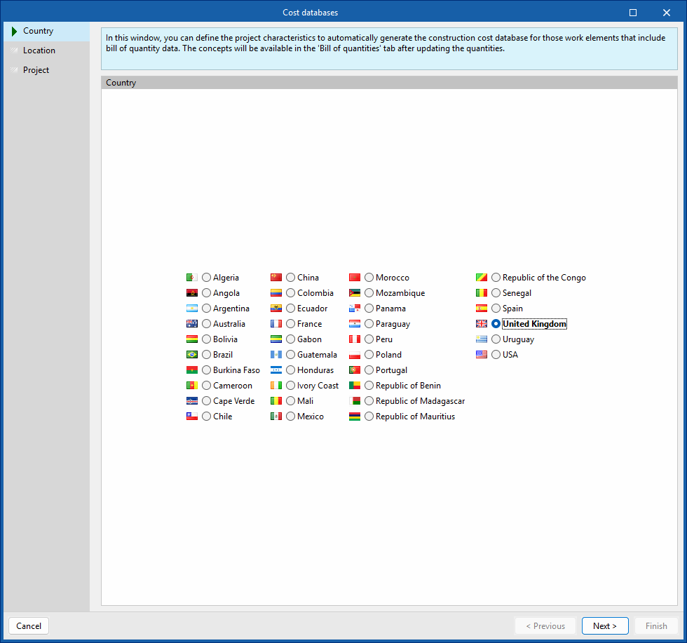
Configuring cost databases
In the "Project" section of the main toolbar on the "Diagrams: Analysis" and "Diagrams: Detail" tabs, you will find the option to configure the program's cost databases.


Cost databases
The "Cost databases" option allows you to define project characteristics to customise the automatic generation of prices for work items that include cost estimate data.
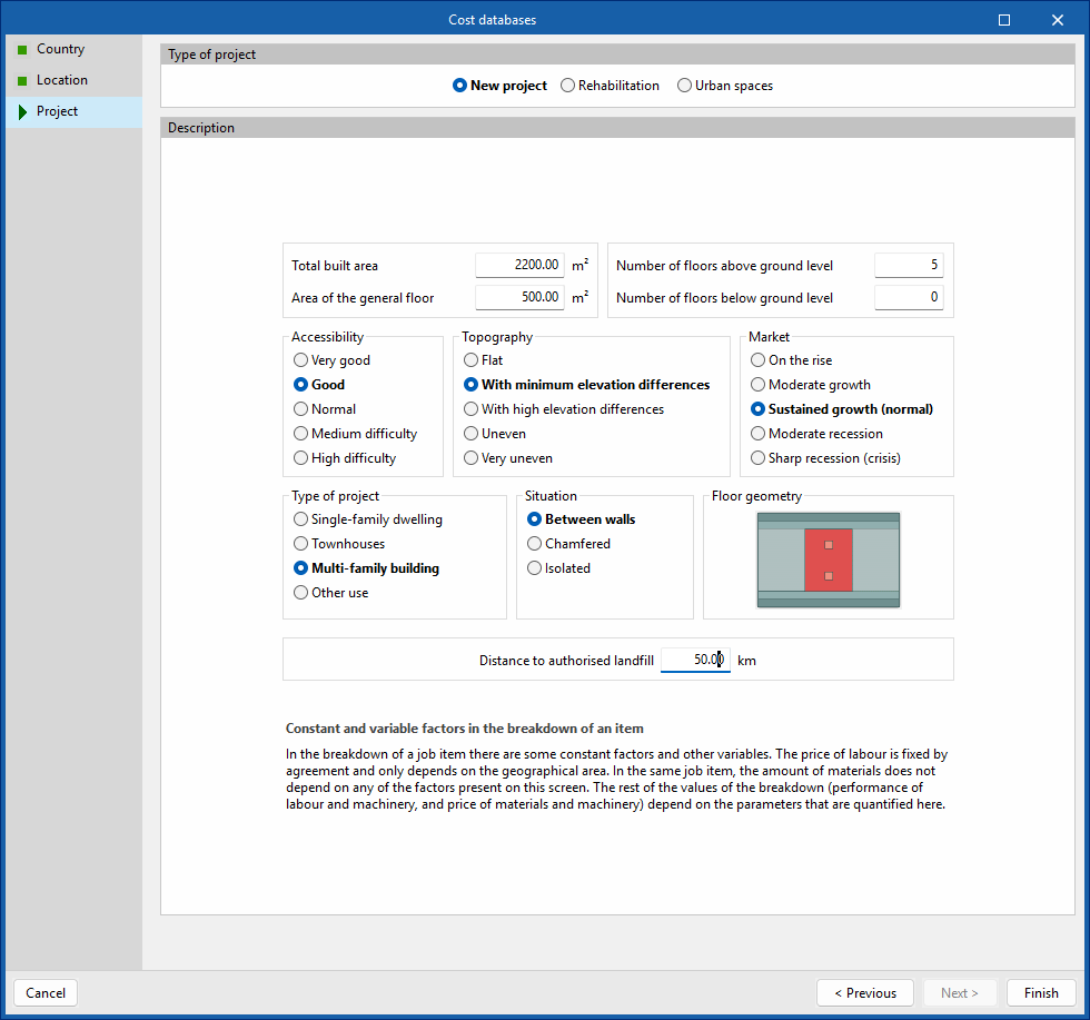
To do this, a wizard opens where the following parameters are defined:
- Country
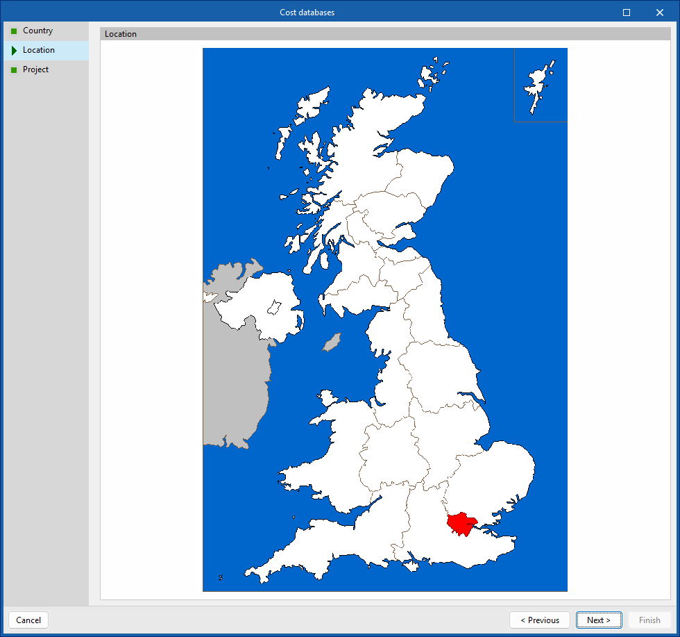
Selects a country. - Location
Selects a location within the specified country. - Project
Specifies the type of project (new build, refurbishment or urban spaces), as well as descriptive parameters such as floor area, accessibility, topography and location of the plot, market conditions, intended use of the project, floor plan geometry and distance to the authorised landfill site. At the bottom, there is a "Technical justification report" detailing the breakdown of the cost of the construction units and the methodology used to determine and update prices.
The selection made adjusts the breakdown of the work items generated by the program, such as the cost of labour and ancillary materials. It also converts the prices into the currency of the selected country.
| Note: |
|---|
| You can select products from the Open BIM Database manufacturer catalogues that include pricing data and place them in the model under the "Diagram: Analysis" and "Diagram: Detail" tabs. At present, this feature is available for the "Splitter" and "PAU Splitter" elements. The program will then automatically generate the prices for the items corresponding to these elements when you switch to the "Bill of quantities" tab and use the "Update the quantities" option. |
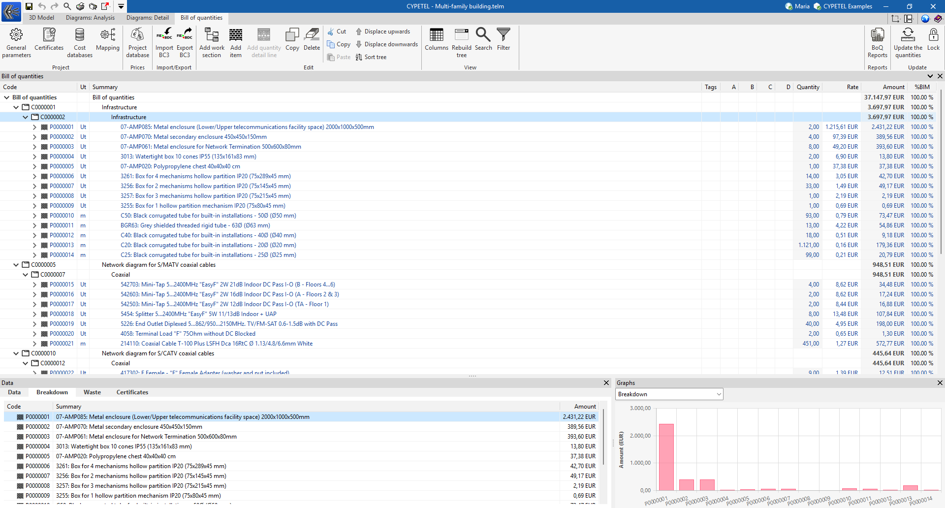
"Bill of quantities" tab

The "Bill of quantities" tab contains tools designed to help you create and manage quantities and bills of quantities.
From this window, you can manage general settings, certificates, cost databases, mapping and project databases. It also offers options for importing and exporting in BC3, manually editing the bill of quantities, managing its display, generating reports and updating quantities, amongst other things.
| More information: |
|---|
| The following link provides detailed information on the "Bill of quantities" tab in Open BIM apps that include it, explaining all the available features in greater detail. |
Results output
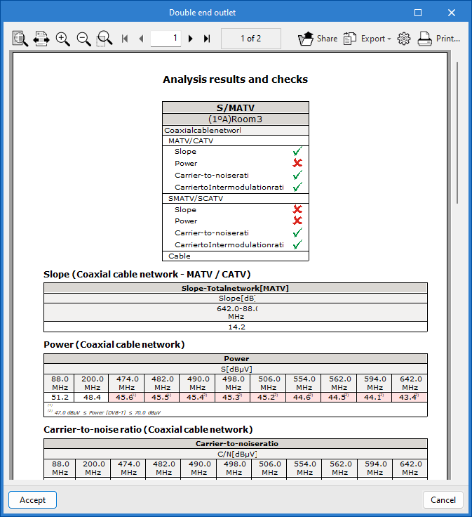
The analysis results can be obtained in the following ways:
Reports
The reports generated as a result of the system analysis can be exported to various formats (TXT, DOCX, PDF, etc.) for printing or modification.
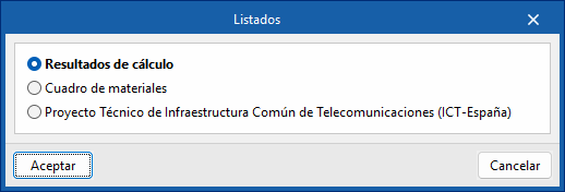
CYPETEL exports several types of reports:
- Analysis results
Report and checks performed by analysing the telecommunications installation. - Materials table
Reports with references, description of the elements entered and their measurements.
Drawings
CYPETEL can generate drawings of the main diagrams, which can be sent to any printing device or exported to different formats such as DWG, DXF or PDF, among others.
Bill of quantities in BC3 and CSV formats
As well as generating "Bill of quantities reports" from the "Bill of quantities" tab, CYPETEL automatically generates the quantities of the installation equipment and can export them to the standard FIEBDC-3 (.bc3) format or CSV format, so that they can be read by any compatible application.
To export to BC3, simply use the "Export to BC3 format" tool in the top toolbar of the interface and assign a name to the file.
Similarly, to export to CSV, simply use the "Export to CSV format" tool in the top toolbar of the interface, assign a name to the file and tick the desired boxes to include associated information (reference, unit, description, etc.).
IFC and GLTF files supported by BIMserver.center
When exporting the project to the BIMserver.center platform, an IFC file and a 3D model in GLTF format are automatically exported for the integration of the building model into the Open BIM project, allowing it to be viewed:
- On the online platform
- In the BIMserver.center application for iOS and Android
- In virtual reality and augmented reality
- In other CYPE programs
Integration into the BIMserver.center platform
Many of CYPE's programs are connected to the BIMserver.center platform and allow collaborative work to be carried out via the exchange of files in formats based on open standards.
Please note that, to work on BIMserver.center, users can register on the platform free of charge and create a profile.
When accessing a program connected to the platform, the program connects to a project in BIMserver.center. This way, the files of the projects that have been developed collaboratively in BIMserver.center are kept up to date.

| More information: |
|---|
| For further details related to using CYPE software via the BIMserver.center platform, please click on this link. |
Options available in CYPETEL
The main options for using the model with other BIMserver.center tools can be found under the "3D Model", "Diagrams: Analysis" and "Diagrams: Detail" tabs in the "BIMserver.center" section of the main toolbar.

Importing and updating BIM models
By clicking the "Update" button, you can update the information contained in the models previously imported into the project or import new models if desired.
You can also update the DXF templates from the BIM model, as well as open a dialogue box to modify the model’s geographical location and reference system.
Exporting the BIM model to share it with other users
By clicking the "Share" button, you can export the information contained in the model created with CYPETEL to BIMserver.center.
During the export process, you can specify details about the files to be exported.